2-36
4.7.2 CRANE CONTROL VALVE CONNECTION DESTINATIONS
Valve name
Port
name
Port destination Port size
Note
Derrick
A Derrick raising port via rotary joint A port G3/4
B Derrick lowering port via rotary joint B port G3/4
Winch
A Winch raising port via rotary joint C port G3/4
B Winch lowering port via rotary joint D port G3/4
Telescoping
A Telescope extension port via rotary joint E port
G3/4
B Telescope retracting port via rotary joint F port
G3/4
Slewing
A Slewing motor A (right) port G3/4
B Slewing motor B (left) port G3/4
P Travel / outrigger control valve T1 port G1
T Return manifold blow-off G1
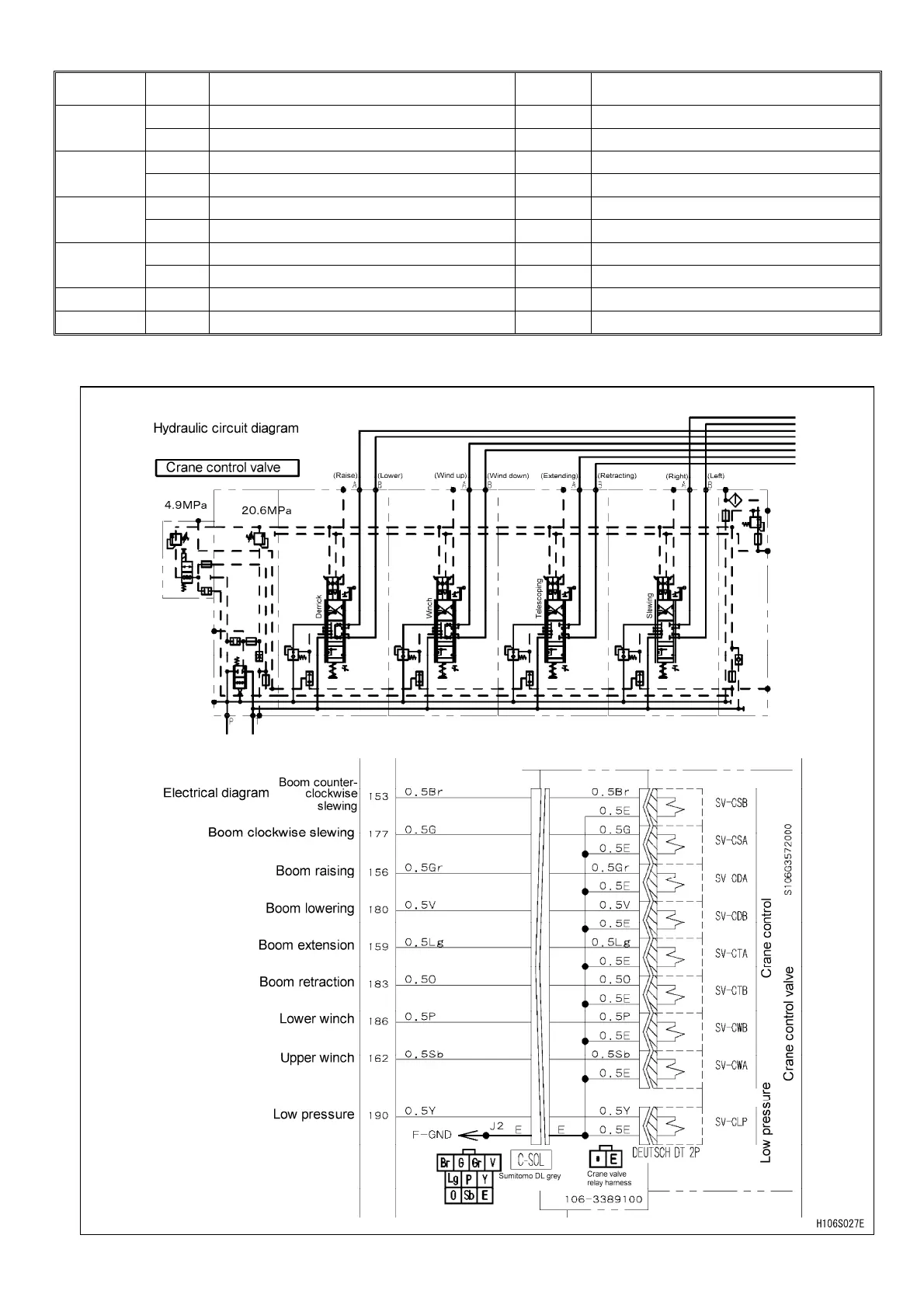
4.7.3 CRANE CONTROL VALVE CIRCUIT DIAGRAM

 Loading...


