GROVE 8-33
CD3340B/YB4411 AXLES/DRIVE SHAFTS/WHEELS AND TIRES
Published 04/07/2015 Control # 569-00
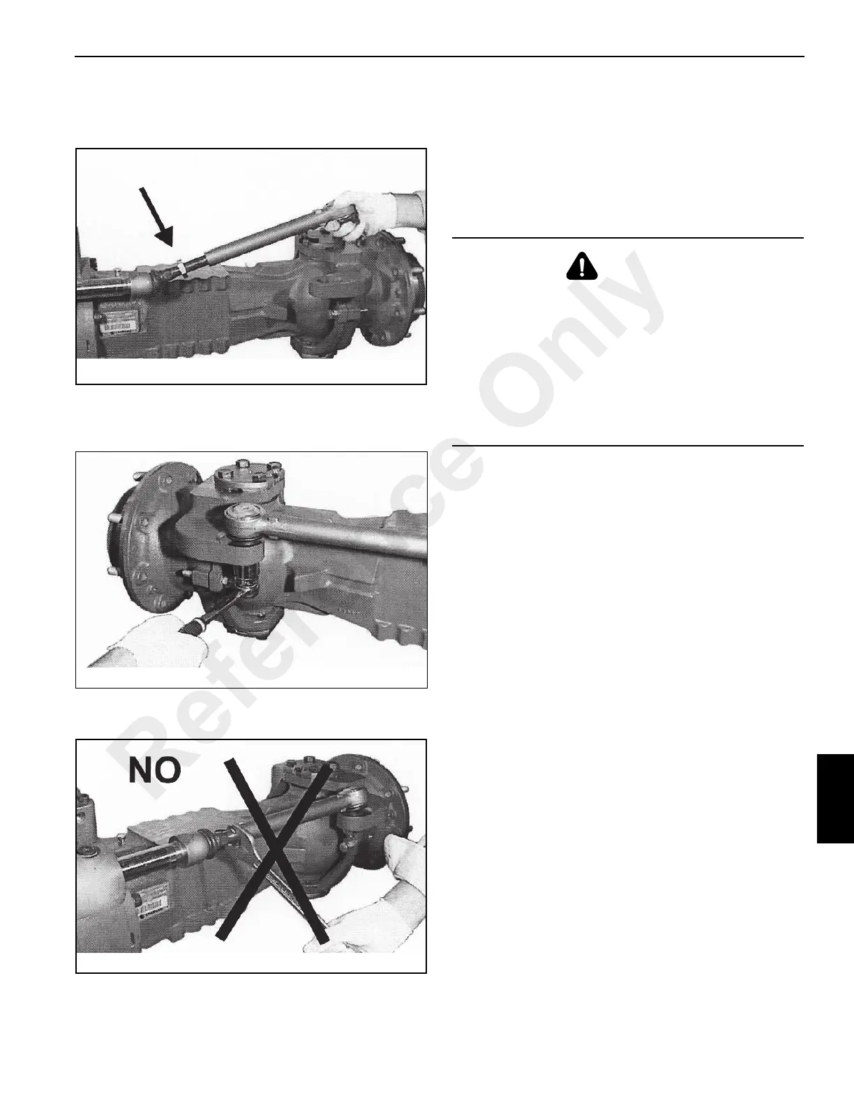
2. Loosen the jam nut on the guide rod and adjust the
guide so that the ball joint can be inserted into the swivel
housing (Figure 8-135).
3. Insert the ball joint in the swivel housing (Figure 8-136).
Install the lock nut and tighten to a torque of 220 Nm
(162 lb-ft).
4. Tighten the jam nut only after the toe-in adjustment has
been performed.
Toe-in Adjustment
See page 8-3 for toe-in adjustment procedures
Steering Angle Adjustment
See page 8-5 for steering angle adjustment.
Installation
1. Position the axle under the frame and install mounting
bolts and nuts. Tighten to a torque of 362 Nm (266 lb-ft).
2. Connect the drive shaft to the axle flange.
3. Connect the hydraulic hoses to the steering cylinder
4. Connect the brake lines to the axle brake housings.
5. Fill the axle differential, brake housings and wheel hubs
with proper lubricant. See Maintenance, page 5-1.
6. Install the rims and tires. Do not lower the tires to ground
until the axle is tested for proper operation.
7. If the axle has been repaired, test the axle for proper
operation:
a. Set the parking brake to lock the pinion shaft.
b. With the help of another person, standing on the
opposite side, begin rotating each wheel forward as
much as possible (both wheels will become blocked
after awhile).
c. Free the right wheel and rotate the left wheel
forward. Rotate the right wheel in opposite direction.
The left wheel will turn freely without difficulty and
the right wheel will turn in the opposite direction if
axle assembly has been performed correctly.
Repeat the procedure in the opposite direction
(reverse gear).
IF ONE OF THE WHEELS DOES NOT ROTATE
FREELY IN BOTH DIRECTIONS, then check step
by step all assembly procedures. Check that the
brakes are installed properly and are functioning
correctly.
WARNING
Crushing Hazard!
A raised and badly supported machine can fall on you
causing severe injury or death. Position the machine on a
firm, level surface before raising one end. Ensure that the
other end is securely chocked. Do not rely solely on the
machine’s hydraulics or jacks to support the machine
when working under it.
Disconnect the battery cables while you’re under the
machine to prevent the engine from being started.
Reference Only
 Loading...


