S
ection
5
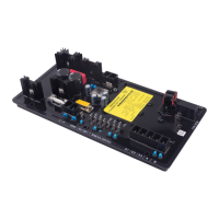
Figure 5-16. Message Box to Return to FCR Nominal Setpoint
PF Tab (Available on DVR2000EC only)
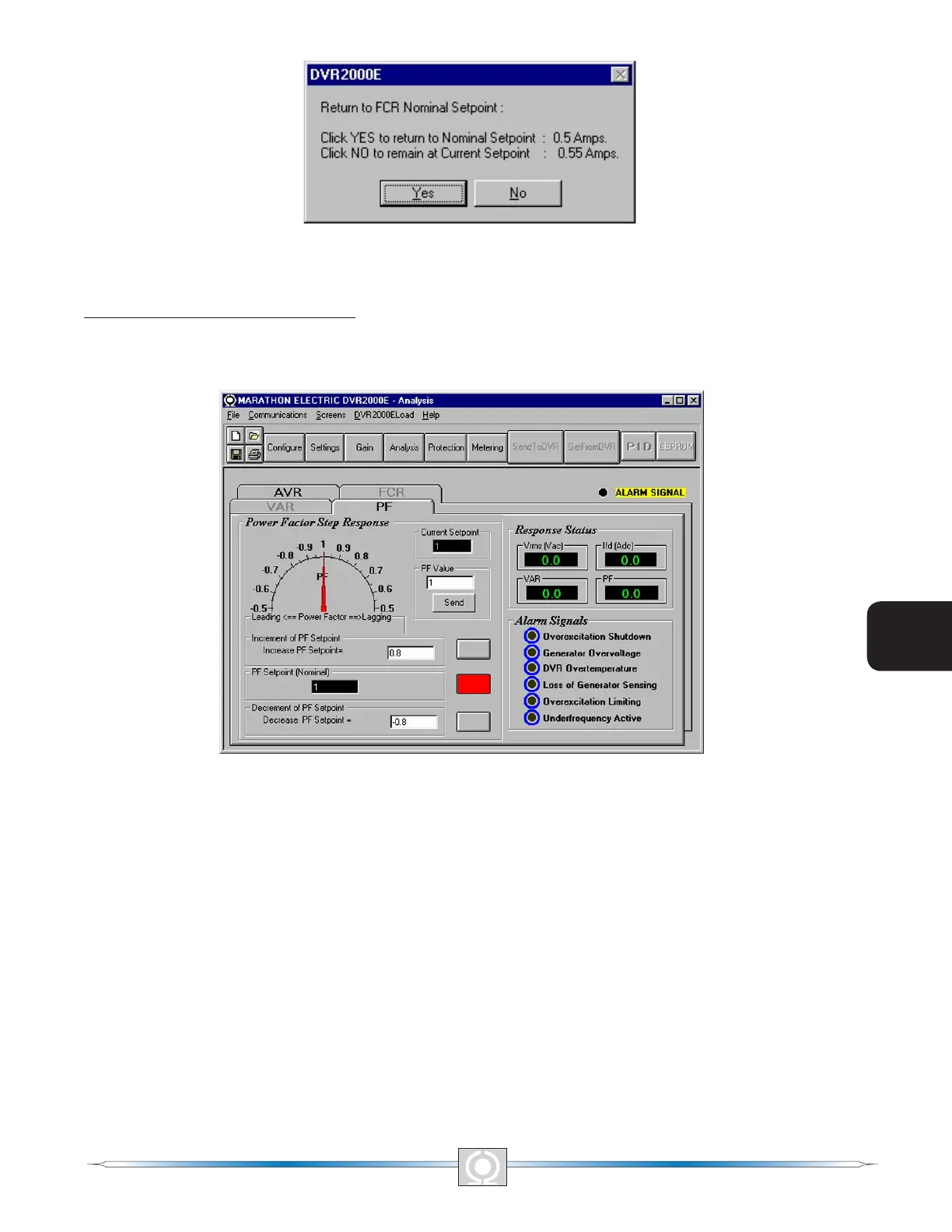
Figure 5-17 illustrates the settings, sensing values, and alarm signal indicators of the PF tab. Each setting of the
PF tab is described in the following paragraphs.
Figure 5-17. Analysis Screen, PF Tab
Power Factor Step Response - Power Factor Setpoint (Nominal). This read-only eld indicates the PF setpoint.
(The PF setpoint is set by using the Setpoint tab of the Setting Adjustments screen). The value displayed in the
PF Setpoint eld is selected by clicking the adjacent button. Clicking this button sends the PF Setpoint value to
the DVR2000E and changes the color of the button from gray to red.
Power Factor Step Response - Increment of PF setpoint. This eld indicate the increase that occurs to the PF
setpoint when the corresponding increment button is clicked. Any setpoint value within the range and higher than
setpoint value can be input to this led. The PF setpoint changes to this value when the adjacent button is clicked.
When clicked, the Increment button changes from gray to red to indicate that the PF setpoint has increased to the
value in the eld.
Power Factor Step Response - Decrement of PF setpoint. This eld indicate the decrease that occurs to the PF
setpoint when the corresponding decrement button is clicked. Any setpoint value within the range and lower than
setpoint value can be input to this led. The PF setpoint changes to this value when the adjacent button is clicked.
When clicked, the Increment button changes from gray to red to indicate that the PF setpoint has decreased to
the value in the eld.
52
3
Main Index
5
Section 5 Index
53
3
Main Index
5
Section 5 Index