S
ection
5
Operation Tab
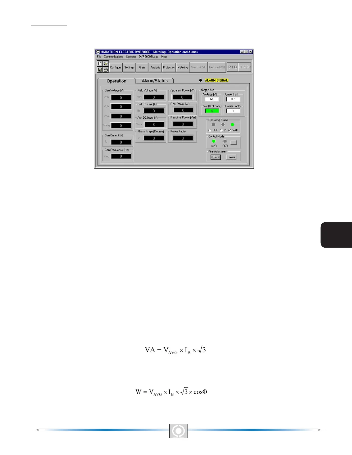
Operation tab metering values, setpoint values and control functions are illustrated in Figure 5-22.
Figure 5-22. Metering, Operation and Alarms - Operation Tab
Gen Voltage (V). These metering values report the status of the V
A-B
, V
C-B
, V
C-A
, and V
AVG
generator voltages and are
the products of the voltage sensed at terminals E1, E2, and E3 and the Generator PT ratio. All metering values are
updated once each second. When single-phase sensing is used (System Conguration screen, Sensing Voltage)
and the DVR2000E sensing voltage terminals (E1, E2, and E3) are connected as shown in Figure 4-7, all of the
generator voltage metering values will be identical.
Gen Current (A). This metering value indicates the level of the B-phase generator current and is the product of
the current input to CT1 and CT2 and the CT ratio. Generator current is monitored through DVR2000E terminals
CT1 and CT2.
Gen Frequency (Hz). This metering value indicates the frequency of the monitored generator voltage.
Field Voltage (V). This metering value indicates the value of voltage being supplied from the DVR2000E output
(terminals F+ and F-) to the generator eld.
Field Current (A). This metering value indicates the amount of current owing from the DVR2000E output
(terminals F+ and F-) to the generator eld.
Aux DC Input (V). This metering value indicates the level of dc control voltage applied from a remote device to
DVR-2000E terminals A and B. The displayed value correlates to the generator voltage setpoint.
Phase Angle (Degree). This metering value indicates the phase angle difference (in degrees) between the
generator voltage and the generator current.
Apparent Power (VA). This value is the calculated product of the metered generator voltage (V
AVG
), metered
generator current (Ib), and the square root of 3. See Equation 5-1.
Equation 5-1. Apparent Power Formula
Real Power (W). This value is the calculated product of the metered generator voltage(V
AVG
), metered generator
current (I
B
), square root of 3 and the cosine of the metered phase angle. See Equation 5-2.
Equation 5- 2. Real Power Equation
56
3
Main Index
5
Section 5 Index
57
3
Main Index
5
Section 5 Index