Chapter 4 EI system diagnosis Section 4 EI system troubleshooting
4—28
Step 2
1)
Turn the ignition switch to the “OFF”position.
2)
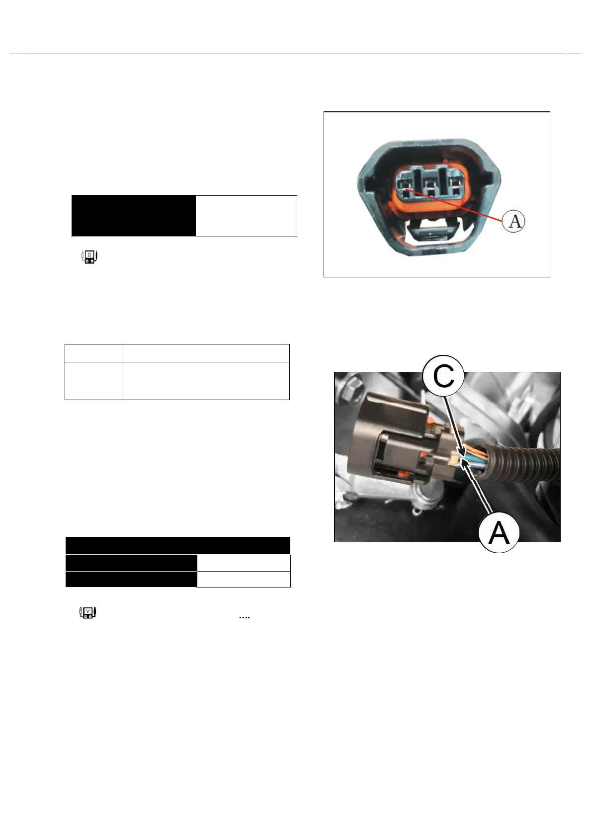
Disconnect the TP sensorcoupler.
3)
Check the continuity between
○
A
(Gr/Bl) andground.
Tester knob indication : Resistance (㏀)
Is the continuity OK?
YES
Go to Step3
NO
Replace the TP sensor with a
new one.
Step 3
1)
Connect the TP sensorcoupler.
2)
Insert the needle pointed probes to the leadwire coupler.
3)
Turn the ignition switch to the “ON”position.
Measure the TP sensor output voltage at
the coupler~between ○
A
(
⊕
:Gr/Bl) and
○
C
(
:G/Bl) by turning the throttlegrip.
TP sensor output voltage
Throttle valve is closed
Approx.0.60~1.00V
Throttle valve is opened
Approx.4.00~4.60V
Tester knob indication:Voltage(—)
TP sensor continuity
Ω
(Infinity)
(
A
- Ground)