Chapter 6 Chassis section 5 Steering
6—26
Install speed odometer.Connect the soft axis of the
speedometer.Make sure the speedometer connector is
properly and securely connected to the connector on the
main harness.Then tighten the waterproof sleeve on the
main line harness with tie strap.Install headlight
assembly.First, connect the headlight connector correctly
and firmly to the connector on the main line
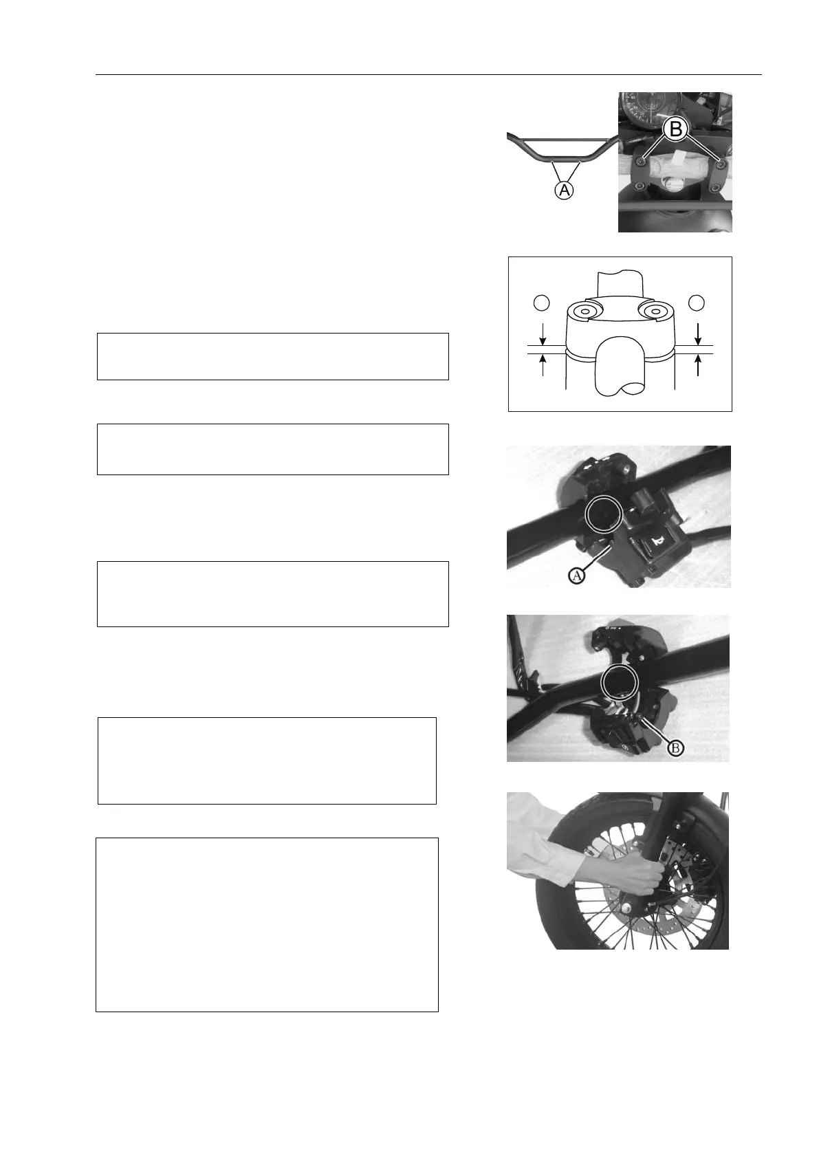
harness.Install the handlebar welding assembly so that
point A is aligned with the pressure handle block B as
shown in Fig.As in Fig.5.5.29.
Tighten anchor block bolts to specified torque.
Stud bolts: 16 N · m (1.6 kg · m)
Note:The clearance between the handle block and the
holder should be even.
As in Fig.5.5.30.
Install the switch with the left hand handle.
Note:
Insert the protruding part A into the handlebar hole.
As in Fig.5.5.31.
Install clutch handle assembly and tighten and adjust
clutch switch line and clutch tension line accordingly.
Install the switch with the right hand handle.
Note:
Insert the protruding part B into the hole of
handle.Apply super grease to the end of the door line.
As in Fig.5.5.32.
Load the main cylinder.
Install the brake.
Install left and right rearview mirrors.
As in Fig.5.5.33.
Fig.5.5.291
Fig.5.5.30
C
Fig.5.5.31
Fig.5.5.32
Fig.5.5.33
Note:
Hold the front shock absorber tubes and move
them back and forth to check that the steering
lever is loose.
Note:After adjusting and loading the handlebars, shake
the front wheel assembly back and forth to ensure no
backlash.
After this procedure has been completed correctly,
check that the steering lever is free of left-right
movement due to its own weight.
If there is significant clearance or inflexibility, re-adjust
the steering rod nut.