Chapter 3 Engine Section 5 Engine reassembly
3—57
Install the connecting sleeve.
As in Fig.3.5.71
Note:
Be sure to check valve clearance.
Check valve clearance
Inlet valve and exhaust valve clearance specifications
are not the same.
Valve clearance (cooling machine) :
Admission: 0.06 0.08 mm
Exhaust: 0.10 0.12 mm
Align line A on the magneto rotor with mark B on the
magneto cover.
Turn the crankshaft counterclockwise with a socket
wrench, and the piston reaches TDC of the compression
stroke as the intake rocker arm falls and rises.
Turn the crankshaft until line B on the magneto rotor
aligns with triangle mark A on the magneto housing.
If there is no clearance, turn the crankshaft once more.
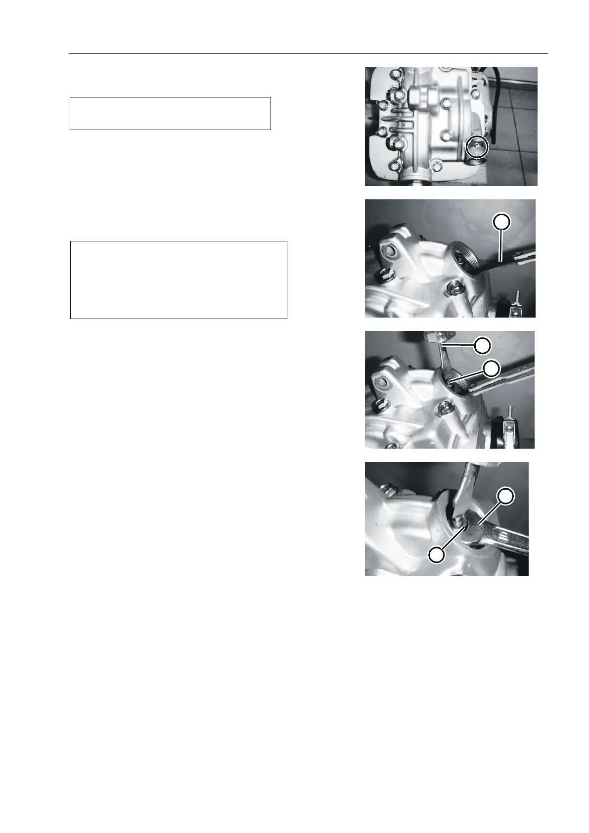
Insert the plug rule into the gap between the stem ①
end and the adjusting screw on the rocker arm.As in
Fig.3.5.72
If the clearance exceeds the specification requirements,
the following requirements should be adjusted.
Adjustment
Loosen the locking nut ⑤.
To use a screwdriver adjusting screw , when ② ③
pulling the feeler ruler is tight, the adjustment ends.As Fig.
3.5.73
Stop turning the adjusting screw and tighten the ③
locking nut ⑤with a spanner④ at the same time to adjust
the valve clearance.As Fig. 3.5.74
Install valve inspection cap, observation hole plug and
magneto cap.
Fig.3.5.71
Fig.3.5.72
Fig.3.5.73
Fig.3.5.74
5
Note:
When checking or adjusting valve
clearance, the piston must be at TDC of the
compression stroke.Check valve clearance
only when the engine is cool.