DP-20 PLUS Web Guide Controller 6-3
4th Quarter 2021 © 2021 Maxcess International. All rights reserved. Figure Sheet 2-320 A
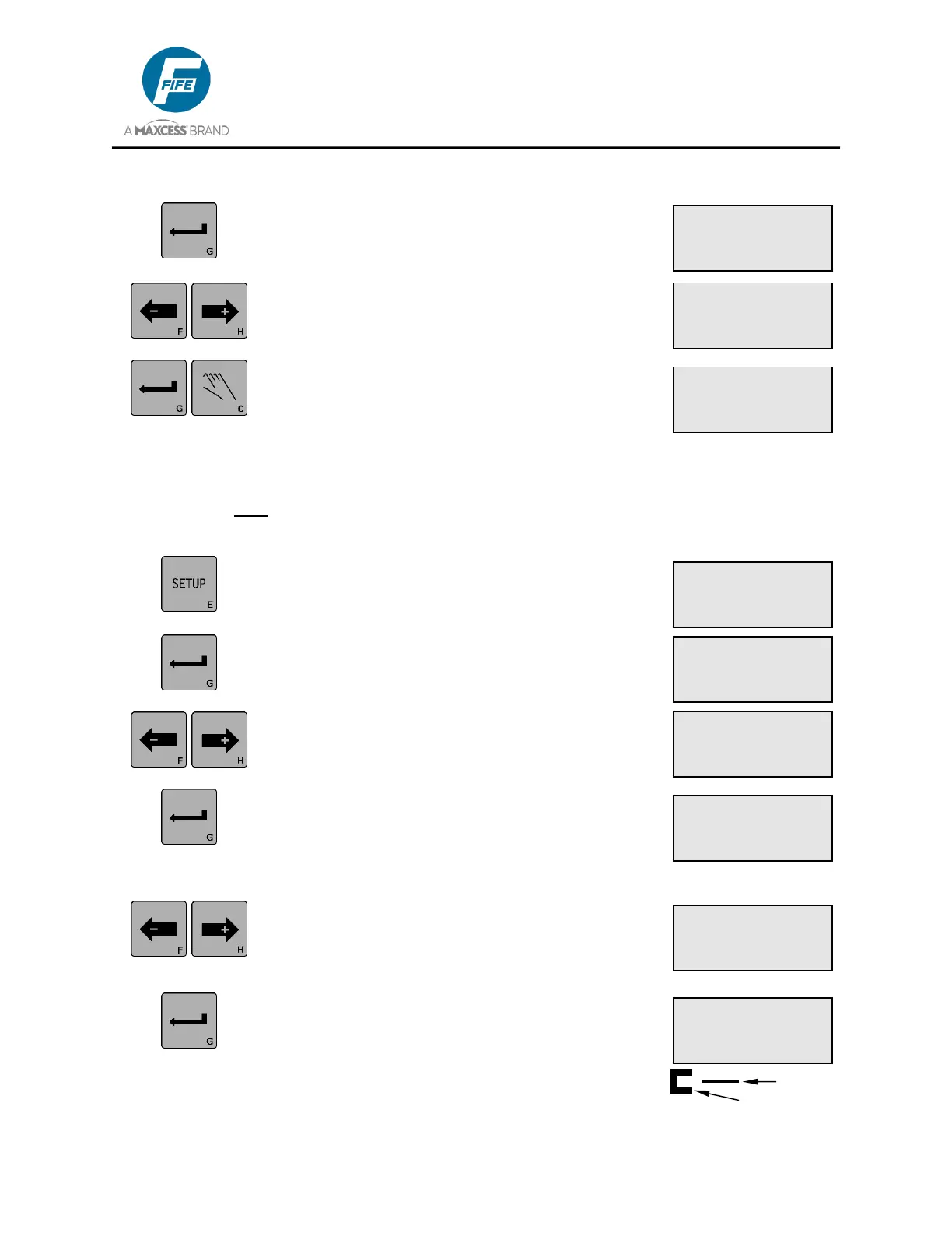
5. Press the ENTER key to allow adjustment of the
Guide Polarity. The current Guide Polarity
setting will begin flashing on line 4.
6. Use the ARROW keys to change the POLARITY
to the desired setting as indicated on Line 4.
7. Press the ENTER key to store the change or
press the MANUAL key to abort the change. The
system will exit the setup menus and return to
the Operator Level.
3X.1.4, Calibration, Edge Sensors
CAUTION: Do NOT perform calibration when using SC-100 capacitance sensor with a DP-20
PLUS.
1. Press the SETUP key to enter the Setup Menus.
The SELECT MENU screen will be displayed on
the LCD Panel.
2. Press the ENTER key to enter the BASIC
Menus. The GAIN menu will be displayed.
3. Use the ARROW keys to scroll until
CALIBRATION is displayed on line 3.
4. Press the ENTER key to enter the
CALIBRATION menu. SELECT SENSOR will be
displayed on line 3. If Center Guiding was the
current sensor mode, the sensor mode is forced
to Edge Left (X4).
5. If necessary, use the ARROW keys to select the
desired sensor (Edge Left or Edge Right) to be
calibrated. The associated sensor connector is
displayed on line 4.
6. Press the ENTER key to begin the calibration.
UNCOVER SENSOR will be displayed on line 2.
Remove all materials from the sensor field of
view (see graphic at right). The sensor signal is
displayed on Line 3.
× 3B.1.4.2
UNCOVER SENSOR
-ÜÜÜÜÜÜÜÜÜÜ+ 0%
× 3A.1.3.1
SETUP (MAN)
GUIDE POLARITY
-
× 3A.1.3.1
SETUP (MAN)
GUIDE POLARITY
+
× 3A.1.1
SETUP (MAN)
GAIN
ãÜÜÜÜÜÜÜÜÜ 10.0%
× 3A.1.4
SETUP (MAN)
CALIBRATION
× 3A.1
SETUP (MAN)
SELECT MENU
BASIC
× 3A.1.4.1
SETUP (MAN)
SELECT SENSOR
(X4)
× 3B.1.4.1
SETUP (MAN)
SELECT SENSOR
(X4)