DP-20 PLUS Web Guide Controller 6-20
4th Quarter 2021 © 2021 Maxcess International. All rights reserved. Figure Sheet 2-320 A
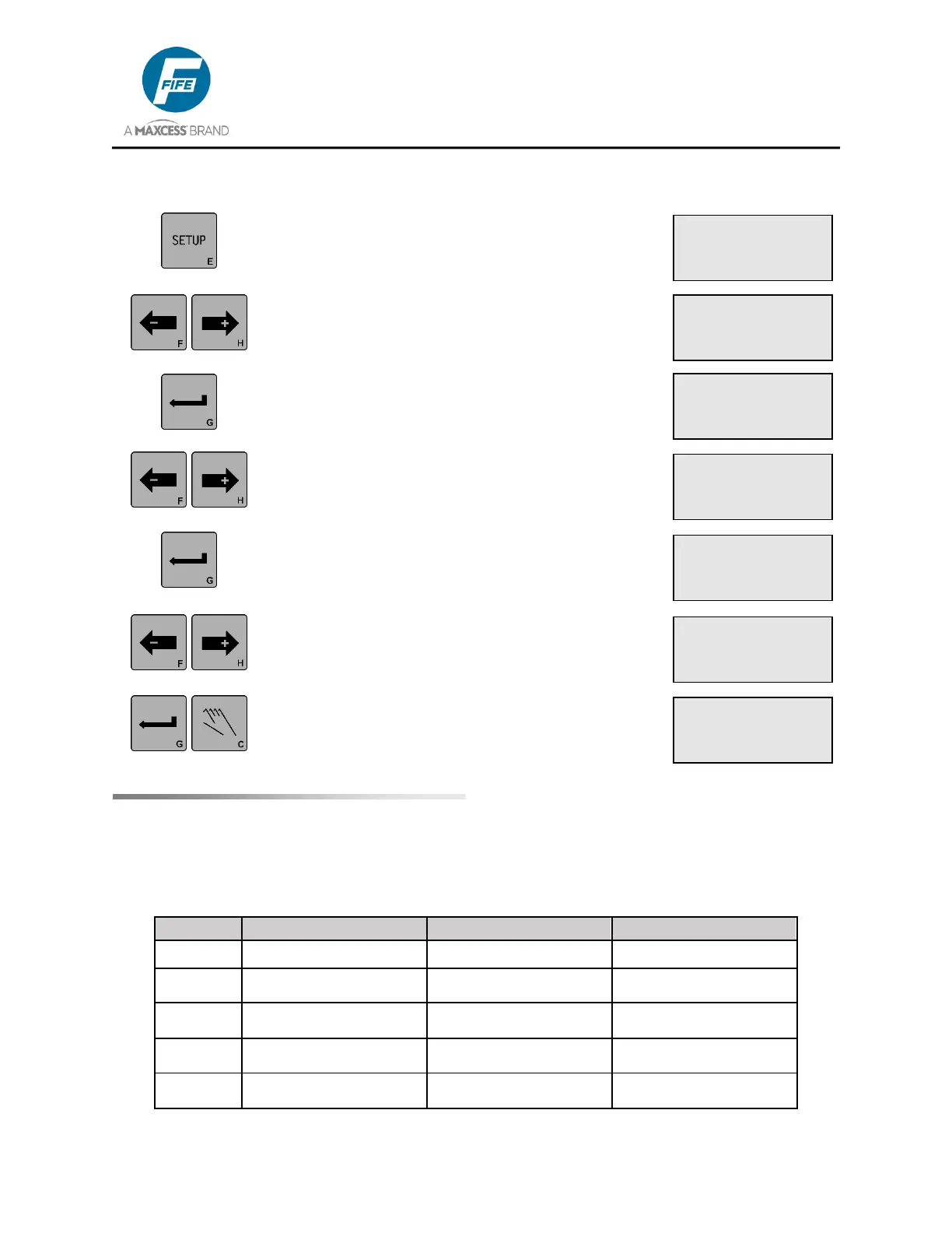
1. Press the SETUP key to enter the Setup Menus.
The SELECT MENU screen will be displayed on
the LCD Panel.
2. Use the ARROW keys to scroll until SPECIAL is
displayed on line 4.
3. Press the ENTER key to enter the Special
Menus. The DEADBAND menu will be
displayed.
4. Use the ARROW keys to scroll until SENSOR
VOLTAGE is displayed on line 3. The current
sensor voltage is displayed on Line 4.
5. Press the ENTER key to enter the SENSOR
VOLTAGE menu. The current sensor voltage
begins flashing on line 4.
6. Use the ARROW keys to scroll to the desired
sensor voltage, +12V or +15V as indicated on
line 4. See Caution below, before selecting
+15V for any sensor.
7. Press the ENTER key to store the change or
press the MANUAL key to abort the procedure.
The system will exit the setup menus and return
to the Operator Level.
Caution: To avoid damage to sensors, do NOT select +15V for any sensor, except those listed
below: If not sure about any sensor and specification is NOT available, contact Maxcess
technical support.
× 3A.1
SETUP (MAN)
SELECT MENU
BASIC
× 3A.2
SETUP (MAN)
SELECT MENU
SPECIAL
× 3A.2.8
SETUP (MAN)
SENSOR VOLTAGE
+12V
× 3A.2.8.1
SETUP (MAN)
SENSOR VOLTAGE
+12V
ý 3A.2.8.1
SETUP (MAN)
SENSOR VOLTAGE
+15V
× 3A.2.1
SETUP (MAN)
DEADBAND
-ÜÜÜÜÜÜÜ+ 0.0%