DP-20 PLUS Web Guide Controller 6-15
4th Quarter 2021 © 2021 Maxcess International. All rights reserved. Figure Sheet 2-320 A
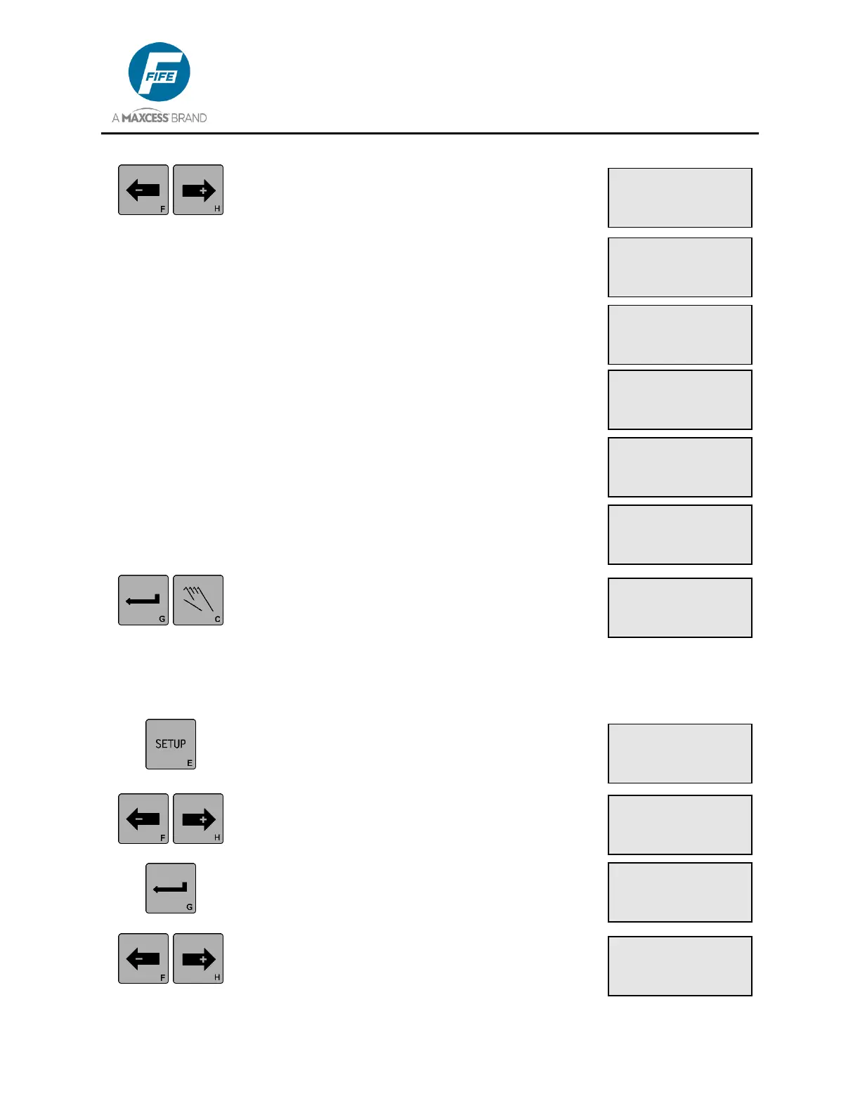
6. Use the ARROW keys to scroll to the desired
selection, as indicated on line 4 of the LCD
Panel. YES, indicates that the corresponding
sensor mode is enabled. NO indicates it is
disabled.
7. Press the ENTER key to store the change or
press the MANUAL key to abort the change. The
system will exit the setup menus and return to
the Operator Level.
3X.2.3, Set Sensor Mode Enable, Line Sensor
1. Press the SETUP key to enter the Setup Menus.
The SELECT MENU screen will be displayed on
the LCD Panel.
2. Use the ARROW keys to scroll until SPECIAL is
displayed on line 4.
3. Press the ENTER key to enter the Special
Menus. The DEADBAND menu will be
displayed.
4. Use the ARROW keys to scroll until SENSOR
ENABLE is displayed on line 3. The current
selection is displayed on Line 4.
× 3A.2.3.2
SETUP (MAN)
| × | Ø | ×Ø |
|YES |YES |NO |
× 3A.2.3.3
SETUP (MAN)
| × | Ø | ×Ø |
|YES |NO |NO |
× 3A.2.3.4
SETUP (MAN)
| × | Ø | ×Ø |
|NO | YES |NO |
× 3A.2.3.5
SETUP (MAN)
| × | Ø | ×Ø |
|YES| NO |YES |
× 3A.2.3.6
SETUP (MAN)
| × | Ø | ×Ø |
|NO |NO |YES |
× 3A.2.3.7
SETUP (MAN)
| × | Ø | ×Ø |
|NO |YES |YES |
ý 3D.1
SETUP (MAN)
SELECT MENU
BASIC
ý 3D.2
SETUP (MAN)
SELECT MENU
SPECIAL
ý 3D.2.1
SETUP (MAN)
DEADBAND
-ÜÜÜÜÜÜÜ+ 0.0%
ý 3D.2.3
SETUP (MAN)
SENSOR ENABLE
| ý | Ł |