DP-20 PLUS Web Guide Controller 7-1
4th Quarter 2021 © 2021 Maxcess International. All rights reserved. Figure Sheet 2-320 A
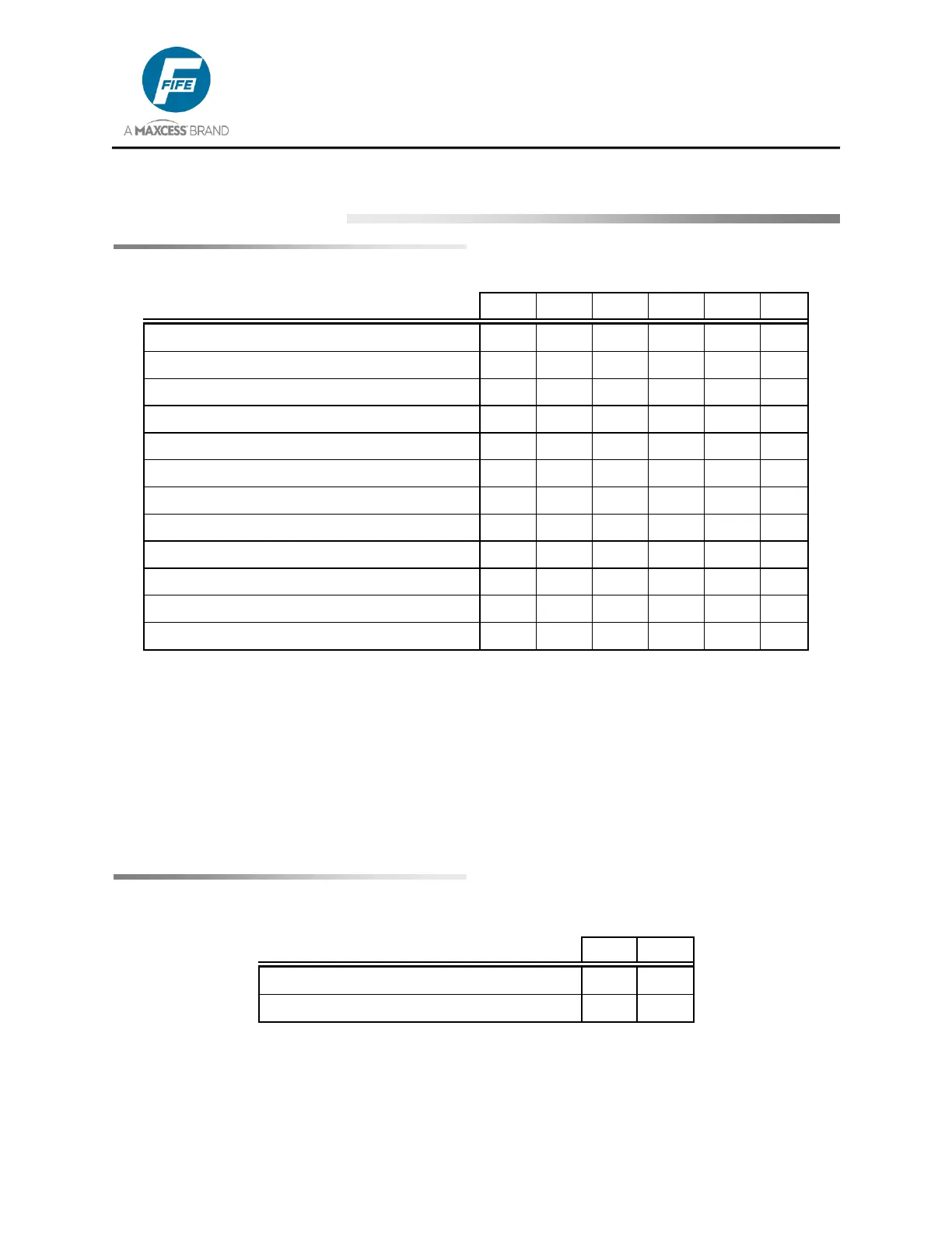
7 PARALLEL MATRIX
Parallel Input Matrix
SENSOR, EDGE L OR LINE CENTER **
SENSOR, EDGE R OR LINE EDGE **
* Inputs 4 & 5 are used to provide Jogs while in Manual and Servo Center modes, and RGPC
functions while in Automatic mode.
** Sensor selection is allowed in Manual and Servo Center modes, only. Sensor selection
must be momentary commands. For sensor selection, input 2 must be commanded either
simultaneously with, or prior to, inputs 1 & 3.
0 = LOW
1 = HIGH
- = IGNORE
Parallel Output Matrix
LOSS OF NULL (AUTOMATIC MODE)
CENTERED (SERVO-CENTER MODE)
* Parallel outputs are active low.
1 = ACTIVE
- = IGNORE