DP-20 PLUS Web Guide Controller 6-30
4th Quarter 2021 © 2021 Maxcess International. All rights reserved. Figure Sheet 2-320 A
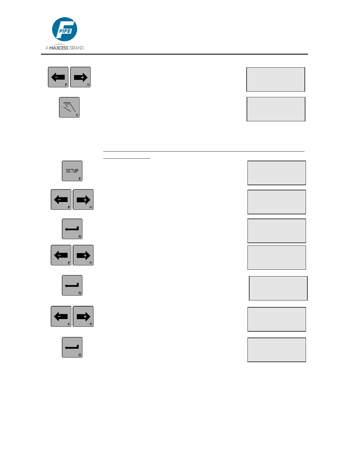
8. Use the left ARROW key to toggle OUT A
between ON and OFF. Use the right ARROW
key to toggle OUT B between ON and OFF.
9. Press the MANUAL key to exit the setup menus
and return to the Operator Level. No settings are
stored, and control of the outputs is returned to
normal.
3X.3.8.3, Test Signals, Guide Test Mode
(THIS MENU IS INTENDED FOR SPECIAL TEST OR APPLICATION
MODES, ONLY).
1. Press the SETUP key to enter the Setup Menus.
The SELECT MENU screen will be displayed on
the LCD Panel.
2. Use the ARROW keys to scroll until
ADVANCED is displayed on line 4.
3. Press the ENTER key to enter the Advanced
Menus. The RESTORE SETTINGS menu will
be displayed.
4. Use the ARROW keys to scroll until TEST
SIGNALS is displayed on line 3.
5. Press the ENTER key to enter the TEST
SIGNALS menu. SENSOR CURRENT will be
displayed on line 3.
6. Use the ARROW keys to scroll until GUIDE
TEST MODE is displayed on line 3.
7. Press the ENTER key to enter the GUIDE
TEST MODE menu. RUNNING will be
displayed on line 2 which indicates that the
oscillator is running. The currently selected
oscillation mode will be displayed on Line 3.
× 3A.1
SETUP (MAN)
SELECT MENU
BASIC
× 3A.3
SETUP (MAN)
SELECT MENU
ADVANCED
× 3A.3.8
SETUP (MAN)
TEST SIGNALS
× 3A.3.8.3
SETUP (MAN)
GUIDE TEST MODE
× 3A.3.8.2.1
SETUP (MAN)
OUT A OUT B
ON ON
× 3A.3.8.3.1
RUNNING
× MODE1 1
-ÜÜÜÜÜÜÜÜ+ 0.50s
× 3A.3.1
SETUP (MAN)
RESTORE SETTINGS
× 3A.3.8.1
SETUP (MAN)
SENSOR CURRENT