DP-20 PLUS Web Guide Controller 6-12
4th Quarter 2021 © 2021 Maxcess International. All rights reserved. Figure Sheet 2-320 A
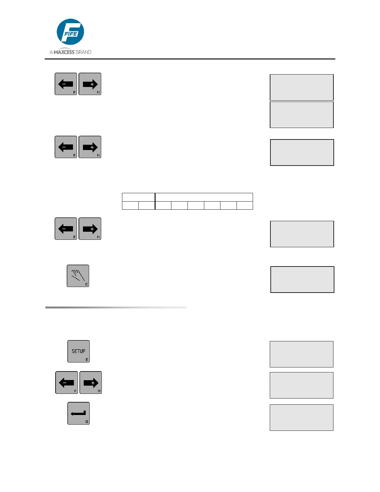
9. Use the ARROW keys to scroll to the desired
Measurement menu. Next in the list is the
MOTOR CURRENT. The motor current value is
displayed on Line 4. Press the ENTER key to
switch between percentage and ampere display
modes. The percentage value shown is relative
to the maximum current of the attached motor.
10. Use the ARROW keys to scroll to the desired
Measurement menu. Next in the list is the
DIGITAL I/O. The state of the digital outputs and
inputs are displayed on Line 4. The order in
which the inputs are displayed is shown in the
following table.
11. If desired, use the ARROW keys to scroll until
EXIT MENUS is displayed on line 3. Pressing
the ENTER key while this screen is displayed
will exit the Measurement Menus and return to
the Operator Level.
12. Otherwise, press the MANUAL key to exit the
Measurement Menus and return to the Operator
Level.
1. Press the SETUP key to enter the Setup Menus.
The SELECT MENU screen will be displayed on
the LCD Panel.
2. Use the ARROW keys to scroll until SPECIAL is
displayed on line 4.
3. Press the ENTER key to enter the Special
Menus. The DEADBAND menu will be
displayed. The current value is displayed on
Line 4.
× 3A.1
SETUP (MAN)
SELECT MENU
BASIC
× 3A.2
SETUP (MAN)
SELECT MENU
SPECIAL
× 3A.2.1
SETUP (MAN)
DEADBAND
-ÜÜÜÜÜÜÜ+ 0.0%
× 3A.1.8.6
MEASUREMENT
MOTOR CURRENT
-ãããÜÜÜ+ +50%
× 3A.1.8.6
MEASUREMENT
MOTOR CURRENT
-ãããÜÜÜ+ +0.15A
× 3A.1.8.7
MEASUREMENT
DIGITAL I/O (X3)
10000000
× 3A.1.8.8
MEASUREMENT
EXIT MENUS
× 3A
MANUAL
×Ø -ãããããáÜÜÜÜ+