DP-20 PLUS Web Guide Controller 4-2
4th Quarter 2021 © 2021 Maxcess International. All rights reserved. Figure Sheet 2-320 A
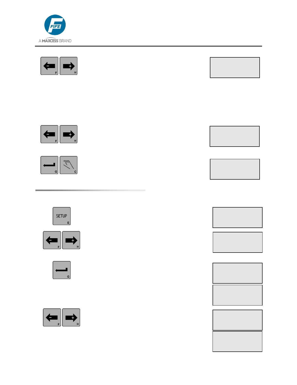
4. Use the ARROW keys to adjust the System
Guide Point to the desired position. The LCD
Panel is scaled to ±100% from the center of the
sensor bandwidth. The default range of the
Guide Point adjustment is ±80% of the sensor
bandwidth, but this range will be limited if a
Deadband above 10% is being used. ASC
settings can also limit the Guide Point range.
The Guide Point change is effective
immediately, but not yet stored.
5. If desired, press both of the ARROW keys
simultaneously to reset the System Guide Point
to the center of the available range, as indicated
on line 4.
6. Press the ENTER key to store the change or
press the MANUAL key to abort the change. The
system will exit setup and return to the Operator
Level. The Guide Point value (GP) will be
displayed on Line 4 if the value is not 0.
1. Press the SETUP key to enter the Setup Menus.
The GAIN menu will be displayed on the LCD
Panel.
2. Use the ARROW keys to scroll until
MEASUREMENT is displayed on line 3.
3. Press the ENTER key to view the Measurement
menus. The level of the guiding signal from the
Left Edge Sensor (Line Center if a line sensor is
being used) is displayed on Line 4. This signal
has been scaled by values determined during
the Sensor Calibration procedure.
4. Use the ARROW keys to scroll to the desired
Measurement menu. Next in the list is the Right
Edge Sensor (Line Edge if a line sensor is being
used). The guiding signal is displayed on Line 4.
This signal is scaled by values determined
during the Sensor Calibration procedure (see
section 6).
×Ø 1C.2.1
SETUP (AUTO)
GUIDE POINT
-ÜÜÜÜåÜÜ+ +20.0%
1C
AUTOMATIC
×Ø -ãããããáÜÜÜÜ+
GP: +20.0%
×Ø 1C.3
SETUP (AUTO)
MEASUREMENT
×Ø 1C.3.1
MEASUREMENT
× SENSOR (X4)
-ããããÜÜÜÜ+ 50%
×Ø 1C.3.2
MEASUREMENT
Ø SENSOR (X5)
-ããããÜÜÜÜ+ 50%
×Ø 1C.1
SETUP (AUTO)
GAIN
ãÜÜÜÜÜÜÜÜÜ 10.0%
×Ø 1C.2.1
SETUP (AUTO)
GUIDE POINT
-ÜÜÜåÜÜÜ+ 0.0%
ý 1D.3.1
MEASUREMENT
ý SENSOR (X5)
-ããããÜÜÜÜ+ 50%
Ł 1E.3.2
MEASUREMENT
Ł SENSOR (X5)
-ããããÜÜÜÜ+ 50%