DP-20 PLUS Web Guide Controller 6-11
4th Quarter 2021 © 2021 Maxcess International. All rights reserved. Figure Sheet 2-320 A
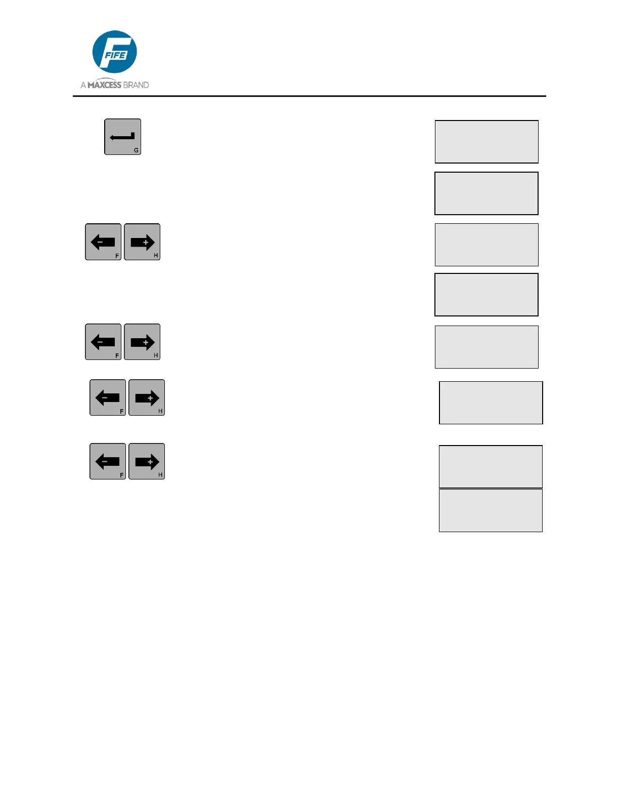
4. Press the ENTER key to view the Measurement
menus. The level of the guiding signal from the
Left Edge Sensor (Line Center if a line sensor is
being used) is displayed on Line 4. This signal
has been scaled by values determined during
the Sensor Calibration procedure.
5. Use the ARROW keys to scroll to the desired
Measurement menu. Next in the list is the Right
Edge Sensor (Line Edge if a line sensor is being
used.) The guiding signal is displayed on Line 4.
This signal has been scaled by values
determined during the Sensor Calibration
procedure.
6. Use the ARROW keys to scroll to the desired
Measurement menu. Next in the list is the
Servo-Center Sensor. The sensor signal is
displayed on Line 4.
7. Use the ARROW keys to scroll to the desired
Measurement menu. Next in the list is the
MOTOR TYPE. The motor type is displayed on
Line 4.
8. Use the ARROW keys to scroll to the desired
Measurement menu. Next in the list is the
TACHOMETER. The motor tachometer signal is
displayed on Line 4. Press the ENTER key to
switch between percentage and RPM display
modes. The percentage value shown is relative
to the maximum speed of the attached motor.
× 3A.1.8.2
MEASUREMENT
Ø SENSOR (X5)
-ããããÜÜÜÜ+ 50%
× 3A.1.8.3
MEASUREMENT
~ƒ SENSOR (X2)
-ããããÜÜÜÜ+ 50%
× 3A.1.8.1
MEASUREMENT
× SENSOR (X4)
-ããããÜÜÜÜ+ 50%
Ł 3E.1.8.2
MEASUREMENT
Ł SENSOR (X5)
-ããããÜÜÜÜ+ 50%
ý 3D.1.8.1
MEASUREMENT
ý SENSOR (X5)
-ããããÜÜÜÜ+ 50%
×Ø 3A.1.8.4
MEASUREMENT
MOTOR TYPE
0.6A MOTOR 8.66K
× 3A.1.8.5
MEASUREMENT
TACHOMETER
-ãããããããá+ +89%
× 3A.1.8.5
MEASUREMENT
TACHOMETER
-ãããããããá+ 1190R