DP-20 PLUS Web Guide Controller 2-3
4th Quarter 2021 © 2021 Maxcess International. All rights reserved. Figure Sheet 2-320 A
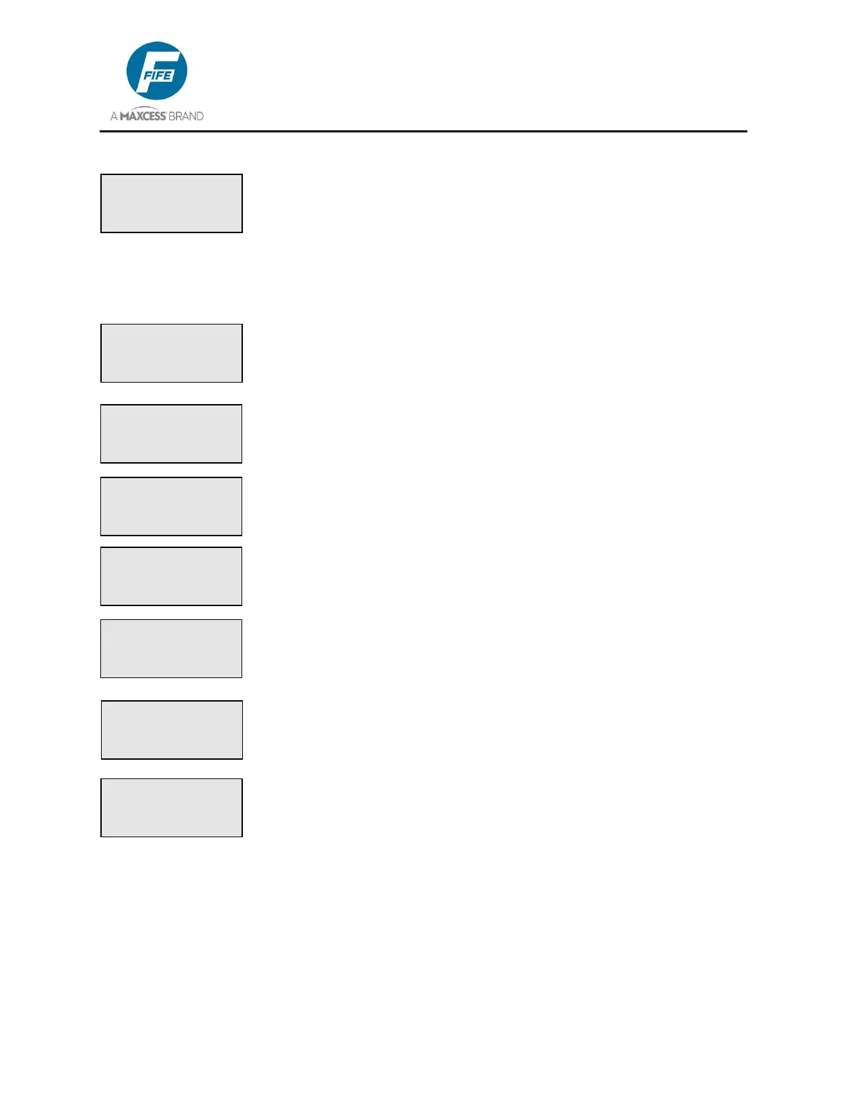
LINE 3 While at the Operator Level, in either Automatic or Manual
mode, this line contains the symbol for the current sensor mode and also
a bar graph indicating the signal level of the currently selected sensor
mode. The sensor symbols are: × indicates Edge Left (X4 port); Ø
indicates Edge Right (X5 port); ×Ø indicates Center Guiding (both edge
sensors, X4 & X5 ports); ý indicates Center of Line guiding (X4 port); and
Ł indicates Edge of Line guiding (X4 port).
LINE 3 While at the Operator Level, in Servo-Center mode, this line
contains the Servo-Center sensor symbol (~ƒ) and also a bar graph
indicating the signal level of the Servo-Center sensor.
LINE 3 While in the Setup Menus, this line indicates the title of the current
menu selection.
LINE 4 While at the Operator Level, this line displays the Guide Point
value, if the value is not zero.
LINE 4 While at the Operator Level, in Automatic or Servo Center mode,
if ASC Control is set to ON, ASC is displayed on this line.
LINE 4 While at the Operator Level, in Automatic mode or Manual mode,
if ASC Control is set to ON, and if either one of the programmed ASC
Limits is reached, this line flashes ASC ACTIVE.
LINE 4 While in the Setup Menus, this line indicates the value
associated with the menu as defined in Line 3. If it is possible to modify
the value, it will be flashing.
LINE 4 While at the Operator Level, in Automatic mode, Servo Center
mode, or Manual mode, if no motor is detected on the Drive connector
(X1), NO MOTOR is displayed on this line.
1C
AUTOMATIC
×Ø -ãããããÜÜÜÜÜ+
× 2A
SERVO CENTER
~ƒ -ãããããÜÜÜÜÜ+
× 3A.1
SETUP (MAN)
GUIDE POINT
-ÜÜÜÜåÜÜ+ +20.0%
1A
AUTOMATIC
× -ãããããáÜÜÜÜ+
ASC ACTIVE
1A
AUTOMATIC
× -ãããããáÜÜÜÜ+
GP: +4.0%
1A
AUTOMATIC
× -ãããããáÜÜÜÜ+
ASC
× 3A.2.2
SETUP (MAN)
GUIDE POINT
-ÜÜÜÜåÜÜ+ +20.0%
3A
MANUAL
× -ãããããáÜÜÜÜ+
NO MOTOR