Chapter 4 Wiring of Servo System
4.1 Servo drive main circuit connection
4.1.1 Main circuit specifications
Name and function of servo drive main circuit terminals are as shown in Table 4-1, the cable specification is as
shown in Table 4-2.
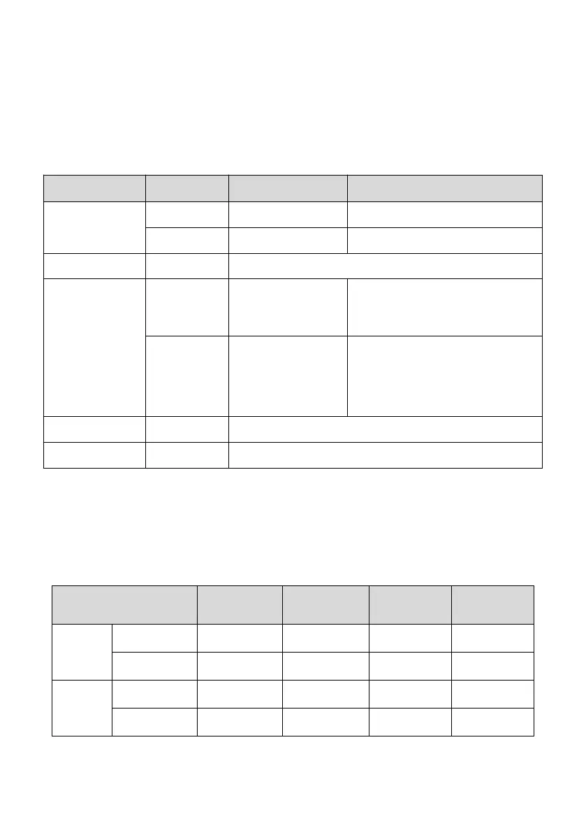
Table 4-1 Name and function of M5-N series drive main circuit terminals
Main circuit power
input terminals
Main circuit single-phase 220V power input
Main circuit three-phase 220V power input
Servo DC bus terminal, can be used for multi-machine common bus
connection
Braking resistor
connection terminals
When the braking capacity is insufficient,
please connect an external braking resistor
between P-PB. Please refer to the
recommended value for specific
specifications.
By default, PB-IR is short-circuited, and the
built-in braking resistor is used; when the
braking capacity is insufficient, disconnect
PB-IR and connect an external braking
resistor between P-PB. Please refer to the
recommended value for specific
specifications.
Servo motor
connection terminals
Connect to U, V and W phases of the servo motor.
Connect to the power supply grounding terminal and the servo motor
grounding terminal for grounding.
Note: PB and IR are short-circuited upon delivery for the drive with built-in resistor.
4.1.2 Main circuit cable dimensions
Recommended main circuit cable dimensions of servo drive are shown in the table below.
Table 4-2 Recommended main circuit cable of M5-N series drive
Power supply
input
L1, L2, L3
 Loading...