Chapter 3 Installation Description
When using an external braking resistor, you need to disconnect the shorting piece between PB and IR,
and connect the resistor between P and PB; if you use an internal braking resistor, you can directly
short-circuit PB and IR.
To protect the drive system and prevent cross-electric shock, please use a circuit breaker or fuse for the
input power supply. The specifications of the circuit breaker and fuse are shown in Table 3-3.
The drive does not have a built-in grounding protection circuit, please use a leakage circuit breaker for both
overload and short circuit protection or a special leakage circuit breaker for bottom line protection.
It is strictly forbidden to directly use the electromagnetic contactor for the operation and shutdown of the
motor. The motor is a large inductance device, and the instantaneous high voltage generated may break
down the contactor and other components.
To ensure reliable operation of the system and reduce interference to the power grid system, it is
recommended to add a filter on the input side.
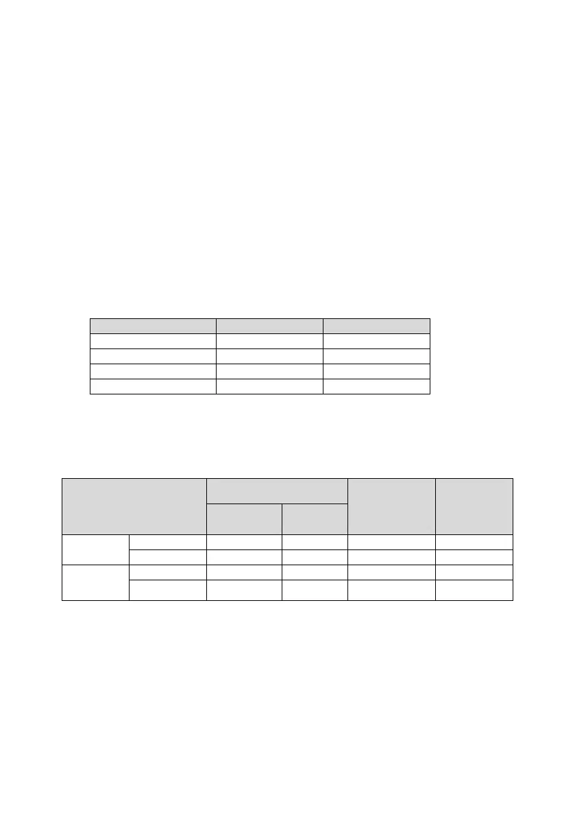
3.4 Recommended specifications for circuit breakers and fuses
Table 3-3 Recommended specifications for circuit breakers and fuses
3.5 Related specifications of braking resistor
The related specifications of braking resistor are shown in the table below.
Table 3-4 Related specifications of braking resistor
Built-in braking resistor
specification
Minimum
allowable
resistance of
external braking
resistor (Ω)
Max. braking
energy
absorbed by
capacitor(J)
Note:
1. Short circuit PB-IR upon delivery, use internal braking resistor.
2. When braking capacity of internal braking resistor is insufficient, disconnect the PB-IR, connect external
braking resistor between PB and P.
3. For external braking resistor, please contact our technical support.
4. "-" in the table indicates that this model has no built-in braking resistor.
 Loading...