Chapter 1 M5-N Servo System Selection
that the capacitor of the bus is charged. Do not touch the power terminal even
if the main power supply is cut off to avoid electric shock.
L1, L2, L3
Main power
supply input
Main power supply input, three-phase 220V.
DC bus terminal for common bus connection
P, PB, IR
Brake resistor
wiring terminal
Braking resistor wiring terminals, please short-circuit PB and IR for internal
braking resistors; connect between P and PB for external braking resistors.
U, V, W
Servo motor
power
terminals
Servo motor UVW power terminal
1.2 Servo system configuration specifications
Table 1-3 Servo motor configuration specification table
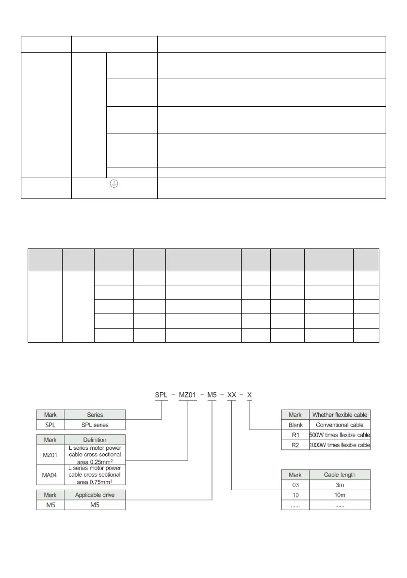
1.3 Applicative cables and models
The model descriptions of the servo system power cable and encoder cable are shown in Fig. 1-7 and Fig. 1-8.
Fig.1-7 Power cable model description
 Loading...