EasyManua.ls Logo

Megmeet M5-N Series User Manual

Default Icon
170 pages
To Next Page IconTo Next Page
To Previous Page IconTo Previous Page
Page #51 background imageLoading...
Page #51 background image
Chapter 7 EtherCAT Communication
51
The process data object (PDO) consists of objects in the object dictionary that can be mapped to by PDO. The
contents of the PDO data are defined by the PDO map. While PDO data is read and written periodically and does
not need to look up an object dictionary, mailbox communication (SDO) is aperiodic and looks up an object
dictionary when reading and writing them.
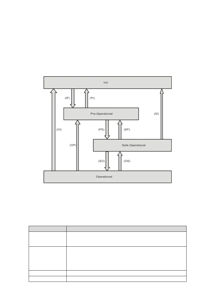
7.2.3 EtherCAT network state machine
EtherCAT state machine is used to describe the state and state changes of the slave application.
State change requests are usually initiated by the master station and responded to by the slave station.
The EtherCAT state machine must support the following four states and coordinate the states between the
master and slave application program during initialization and operation.
These four states are Init (I), Pre-Operational (P), Safe-Operational (S), and Operational (O).
Transition from "Init" to "Operational" must be in the sequence of "Init Pre-Operational Safe-Operational
Operational". Transition from "Operational" to "Init" can be done with certain states skipped. The following table
lists the state transition and the initialization process.
State
Description
Init (I)
Communication initialization;
No communication in the application layer, EtherCAT slave controller (ESC)
register can only be read/written by the master.
IP
Slave address configured by the master;
Mailbox channel configured;
Distributed clock (DC) configured;
Check whether the mailbox is successfully initialized.
Request for Pre-Operational state.
Pre-Operational (P)
Mailbox data communication in the application layer (SDO)
PS
Mailbox initialization process data mapping used by the master;

Table of Contents

Questions and Answers:

Megmeet M5-N Series Specifications

General IconGeneral
BrandMegmeet
ModelM5-N Series
CategoryServo Drives
LanguageEnglish

Summary

Foreword

Precautions for Unpacking Inspection

Check product condition upon receiving, including damage and component integrity.

Safety Precautions

Critical Safety Instructions

Essential warnings on electrical hazards, installation, and operation to prevent injury.

Chapter 1 M5-N Servo System Selection

Servo Motor and Drive Model Selection

Guide to selecting appropriate servo motor and drive models based on series and specifications.

Chapter 2 Servo System Specifications

Servo Drive Electrical Specifications

Details electrical parameters for M5-N servo drives, covering voltage, current, and power levels.

Servo Motor Standard Specifications

Provides basic and rated specifications for M5-N servo motors, including protection and insulation class.

Chapter 3 Installation Description

Servo Drive Installation Guide

Guidelines for installing the servo drive, including site requirements and environmental conditions.

System Wiring Diagrams

Visual representation of wiring for single-phase 220V and three-phase 220V servo systems.

Chapter 4 Wiring of Servo System

Servo Drive Main Circuit Connection

Details on connecting the main power and motor circuits for the servo drive.

Chapter 6 Commissioning Instructions

Pre-Operation Checks

Essential checks before powering on and operating the servo system to ensure safety and proper function.

Commissioning Procedures

Steps for performing jog commissioning and initial setup of the servo system.

Chapter 7 EtherCAT Communication

M5-N Drive EtherCAT Functionality

Details M5-N drive implementation of EtherCAT communication and CiA402 profile.

CiA402 Device Control Protocol

Explains CiA402 device control states, state machine, and object dictionary structure.

Chapter 8 Drive Parameter Object

M5-N Drive Parameter Index

Organized listing of M5-N drive parameters by group, index, and sub-index for configuration.

User Unit Selection for Control

Guide for selecting user units for position, speed, and torque control parameters.

Chapter 9 Troubleshooting

Fault Code Er.001 Drive Overcurrent

Troubleshooting steps for drive overcurrent faults, including causes and solutions.

Alarm Code AL.012 Motor Overload

Common causes and recommended solutions for motor overload alarms encountered with the drive.

Related product manuals