Chapter 6 Commissioning Instructions
6.4 Brake settings
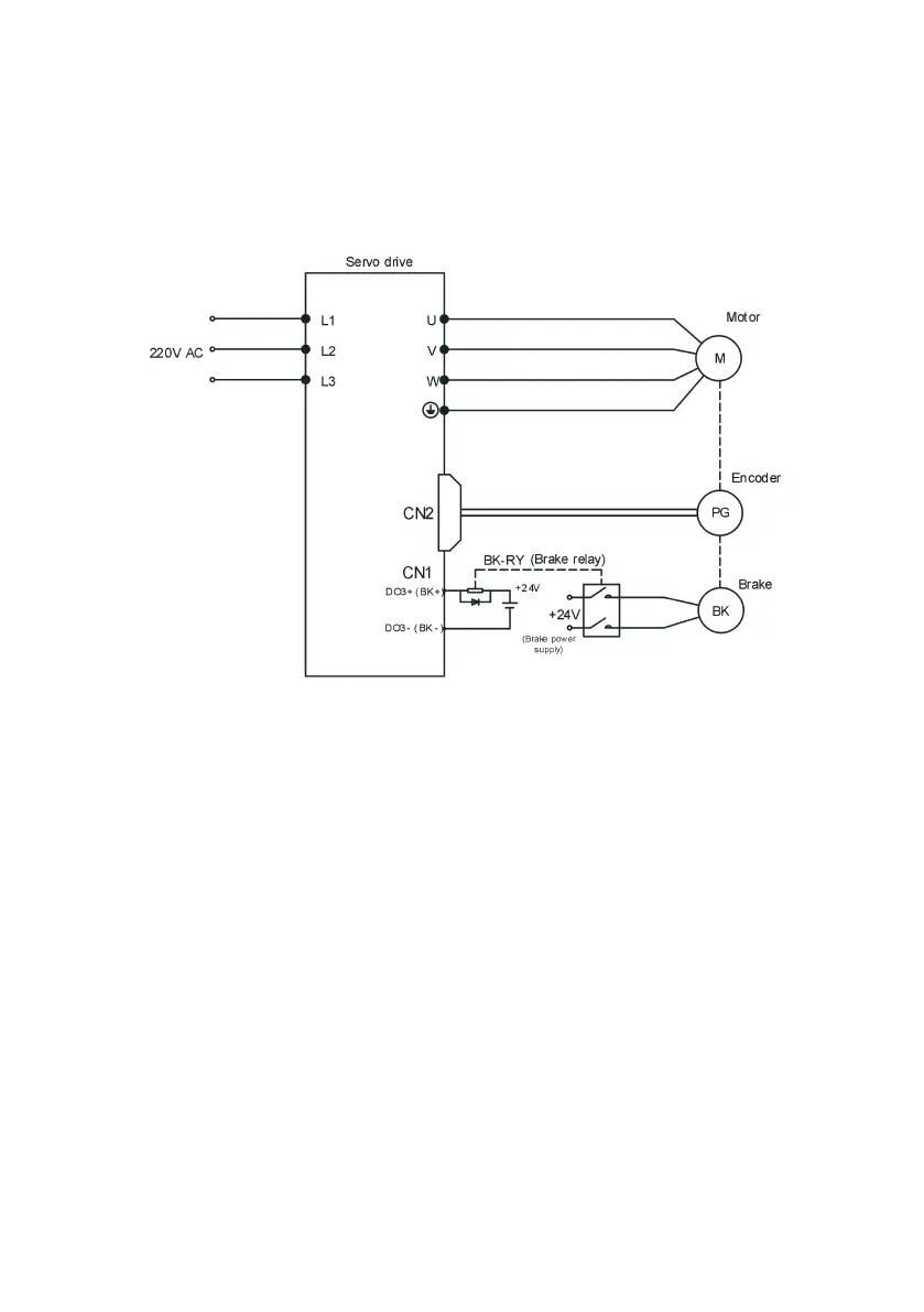
6.4.1 Servo motor brake wiring diagram
The brake signal connection has no polarity. The customer needs to prepare a 24V power supply. The standard
connection of the brake signal BK and the brake power supply is as follows:
Fig.6-3 Brake wiring diagram
Note: It is best not to share the power supply with other electrical appliances to prevent the brake from
malfunctioning due to voltage or current reduction due to the work of other electrical appliances.
6.4.2 Brake timing
For servo motor with brake, a DO terminal of servo drive shall be configured to function 18 (brake output signal)
and determine the valid logic of DO terminal.
According to the current state of the servo drive, the operation timing of the brake mechanism can be divided into
servo drive "normal state" brake timing and servo drive " fault state" brake timing.
The brake timing of the normal state is divided into "motor stationary" and "motor rotation" two cases:
a. Stationary: Motor actual speed is lower than P02.12;
b. Rotation: Motor actual speed is higher than the P02.12 and above.
6.4.3The brake timing when the servo motor is stationary
When the servo enable changes from ON to OFF, if the current motor speed is lower than P02.12, the drive
operates in accordance with stationary timing.
 Loading...