INBOARD (MIE) MODELS
SERVICE MANUAL NUMBER 22
90-860074--1 FEBRUARY 2002 Page 2B-13
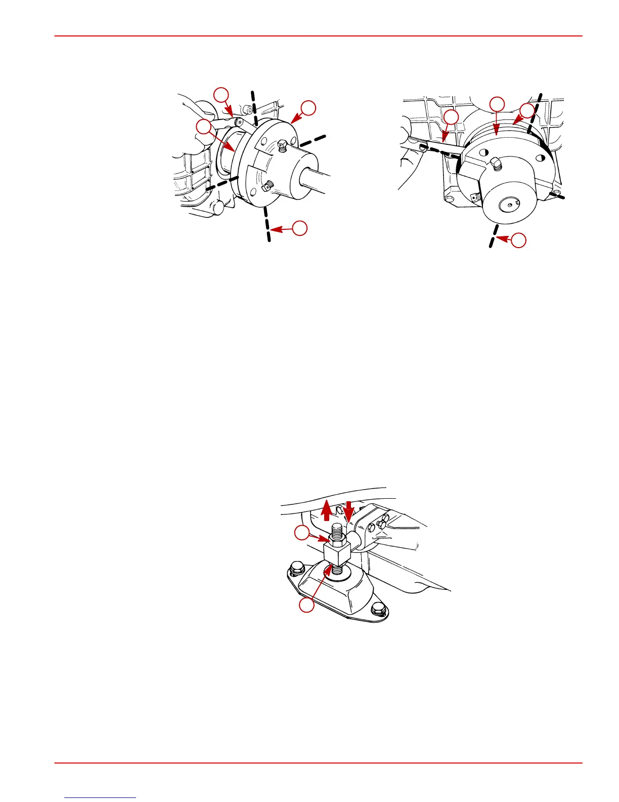
4. Check for angular misalignment, by hand holding coupling faces tightly together and
checking for a gap between coupling faces with a 0.07 mm (0.003 in.) feeler gauge at
90 degree intervals.
50688
a
b
c
d
50608
a
b
c
d
Typical Down Angle Transmission
(All Similar)
Typical V-Drive
a-Propeller Shaft Coupler
b-Feeler Gauge
c-Transmission Output Flange
d-Check Point Intervals
5. If coupling centerlines are not aligned or if coupling faces are more than 0.07 mm
(0.003 in.) out of parallel, adjust engine mounts as follows:
a. TO ADJUST ENGINE UP OR DOWN: Loosen locking nut on mounts requiring
adjustment and turn both front mount or rear mount adjusting nuts equally.
IMPORTANT: Both front mount or rear mount adjusting nuts must be turned equally
to keep engine level from side to side.
23161
a
b
Front Mount Shown (All Similar)
a-Locking (Jam) Nut
b-Adjusting Nut
 Loading...


