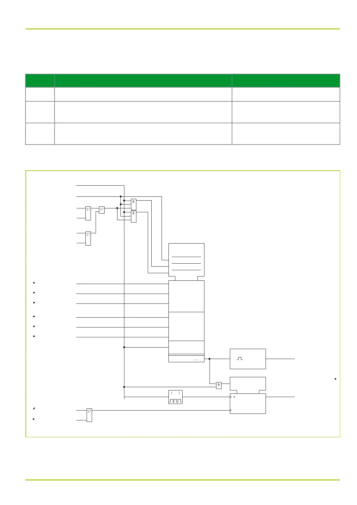
displayed at the end of the fault. If several protection functions detect a fault
then the criterion is selected on the basis of the priorities given in the table
below. The selected criterion is displayed at the P631.
Priority Function Recognizing the Fault Acquisition Time Criterion
1 Differential protection function Maximum differential current
2 Definite-time overcurrent protection or inverse-time
overcurrent protection
Maximum restraining current
3 Functions according to the selection through m out of n
parameters
End of fault
The difference in time between the start of the fault and the fault data
acquisition time is determined by the P631 and displayed.
61Z8056A
FT_DA:
Run time to meas.
[ 004 199 ]
FT_DA:
Save measured values
305 052
MAIN:
General reset USER
[ 003 002 ]
1: execute
MAIN:
Reset LED
306 020
FT_DA:
Fault determ. with
[ 004 198 ]
1: Max. diff. current
1
2
3
5: Max. restrain. curr.
6: Other trigger
31
c1
c2
c3
DIFF:
Id,1
303 303
FT_RC:
Record. in progress
[ 035 000 ]
DIFF:
Trip signal
[ 041 075 ]
DTOC1:
General starting
[ 035 128 ]
DTOC2:
General starting
[ 035 234 ]
IDMT1:
General starting
[ 038 115 ]
IDMT2:
General starting
[ 038 135 ]
DIFF:
Id,2
303 304
DIFF:
Id,3
303 307
DIFF:
IR,1
303 305
DIFF:
IR,2
303 306
DIFF:
IR,3
303 308
c
G
R
Fig. 3-71: Determination of the fault data acquisition time
3 Operation
P631
P631/EN M/R-11-C // P631-310-650 3-101