CTS:
blocked
460 400
IA,y
IB,y
IC,y
Ipos
Ineg
Ineg/Ipos
c
CTS:
Ineg/Ipos> PSx
[ * ]
c
CTS:
Ineg/Ipos>> PSx
[ * ]
c
CTS:
Ipos> PSx
[ * ]
Parameter
set 1
set 2
set 3
set 4
CTS:
Ipos> PSx
001 111
001 115
001 116
001 117
CTS:
Ineg/Ipos> PSx
001 102
001 103
001 104
001 105
CTS:
Ineg/Ipos>> PSx
001 122
001 123
001 124
001 125
64Z5302A
Ipos>,y
Ineg/Ipos>,y
Ineg/Ipos>>,y
MAIN:
Phase sequence
[ 010 049 ]
*
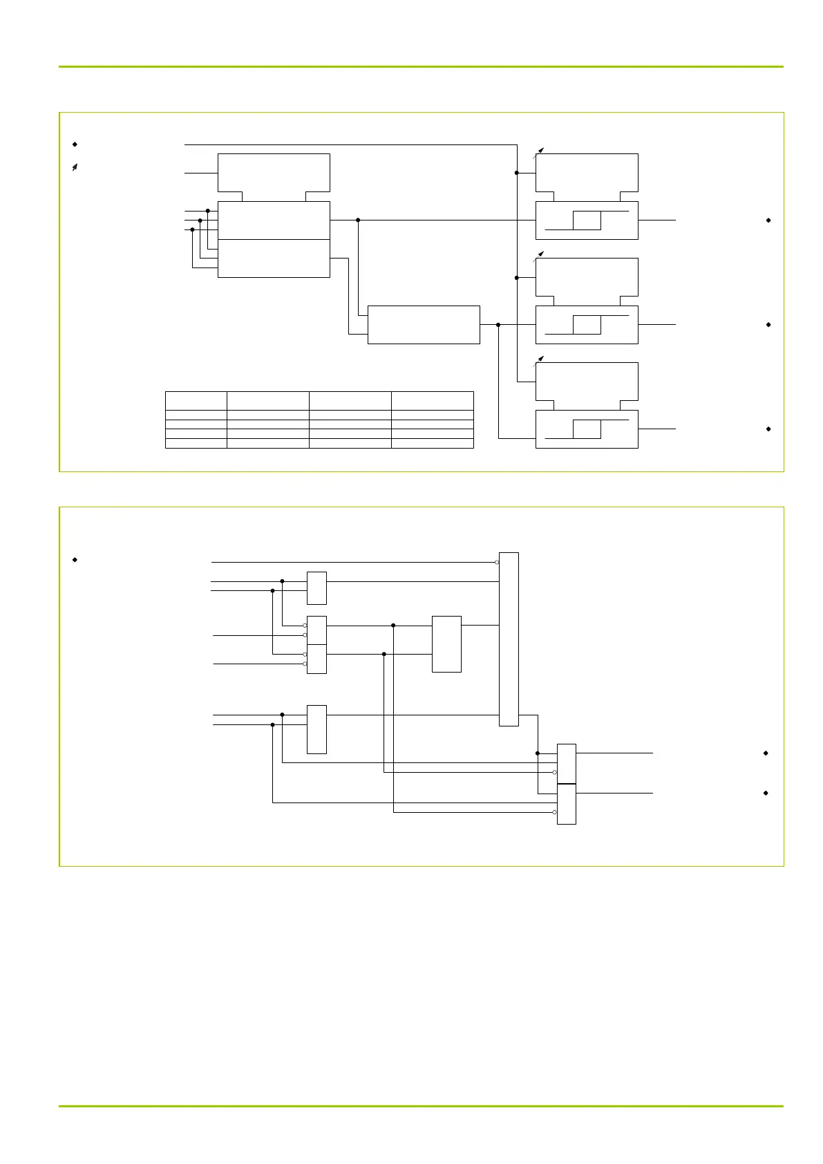
Fig. 3-118: Current evaluation referring to the respective end
62Z5303A
CTS:
blocked
460 400
Ipos>,a
Ineg/Ipos>,a
Ipos>,b
Ineg/Ipos>,b
Ineg/Ipos>>,a
Ineg/Ipos>>,b
=(N-1)
&
&
CTS:
End a faulty
460 471
&
CTS:
End b faulty
460 472
≥1
≥1
≥2
=1
Fig. 3-119: CTS triggering condition
N represents the number of transformer ends, that is N = 2 (a, b).
3.25.5 Signaling and Indication
Triggering of the CTS function is signaled by multiple signals as well as by single
signals referring to the respective ends. Beside the updated signals latched
signals are also available in order to achieve stable signaling behavior and a
permanent differential protection characteristic with reduced sensitivity when,
for instance, intermittent faults have occurred. The updated signal as well as the
stored signal are time-delayed in order to suppress any signaling caused by a
3 Operation
P631
P631/EN M/R-11-C // P631-310-650 3-153