64Z5019A
Parameter
set 1
set 2
set 3
set 4
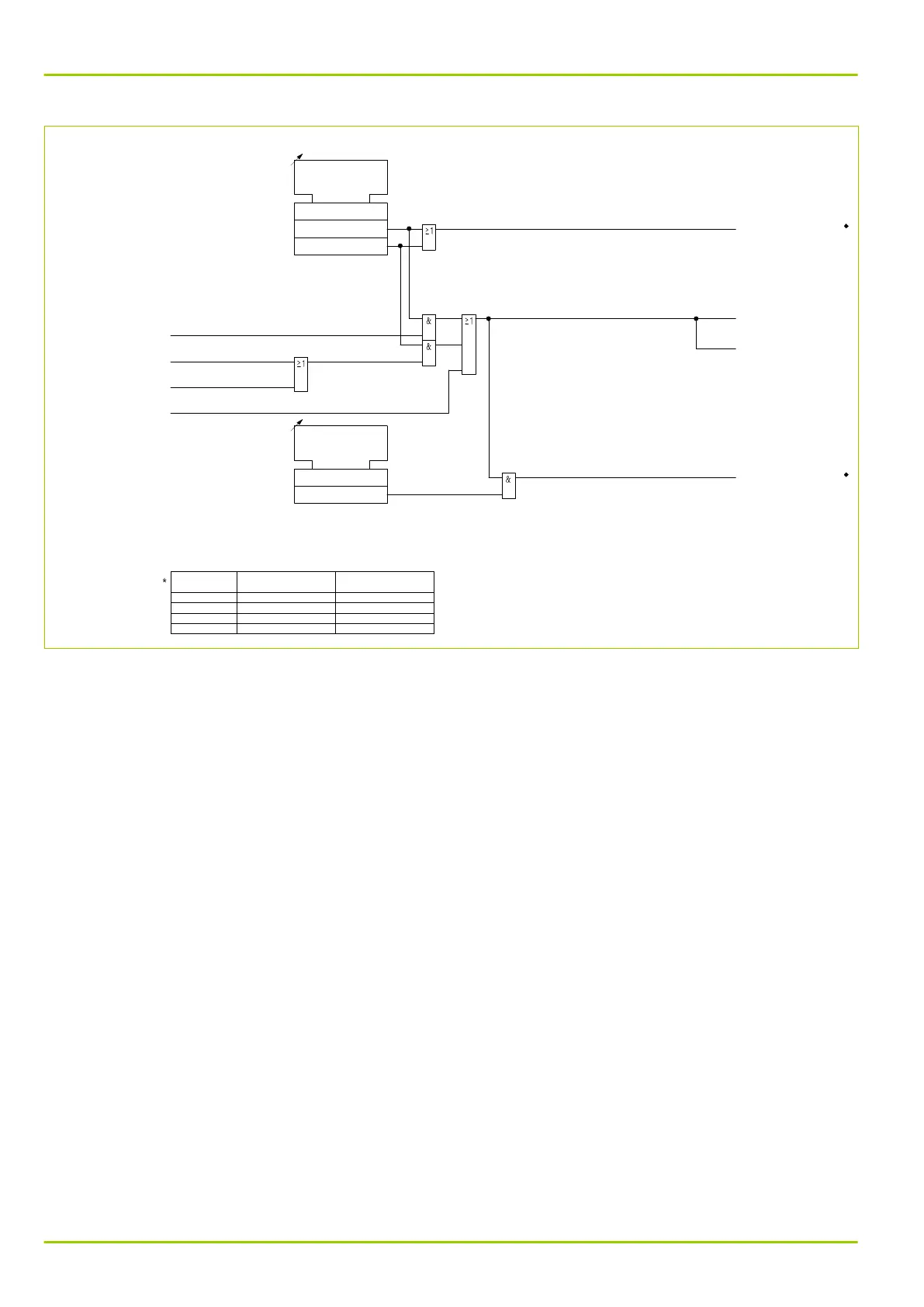
THRM1:
Select CTA PSx
081 072
082 072
083 072
084 072
THRM1:
Bl. f. CTA fault PSx
081 073
082 073
083 073
084 073
THRM1:
Bl. f. CTA fault PSx
[ * ]
1
0
0: No
1: Yes
THRM1:
Select CTA PSx
[ * ]
1
0
2
0: Default temp. value
1: From PT100
2: From 20 mA input
SFMON:
CTA error THRM1
[ 098 036 ]
THRM1:
CTA error
[ 039 127 ]
THRM1:
With CTA
305 222
THRM1:
Block. by CTA error
305 221
MEASI:
PT100 faulty
[ 040 190 ]
THRM1:
CTA error EXT
[ 039 152 ]
MEASI:
Overload 20mA input
[ 040 191 ]
MEASI:
Open circ. 20mA inp.
[ 040 192 ]
Fig. 3-113: Monitoring the coolant temperature acquisition (ambient temperature input)
3.24.5 Warning Signal
A warning signal is issued when the thermal load reaches the warning level set at
THRM1: Rel. O/T warning PSx. Moreover, a time-to-tripping threshold (pre-
trip time) can be set. When the time left until tripping falls below the setting at
THRM1: Warning pre-trip PSx, a warning signal will be issued.
If the current falls below the default threshold of 0.1 I
ref
, the buffer is discharged
with the time constant set at THRM1: Tim.const.2,<Ibl PSx. The thermal
replica may be reset from the local control panel or via an appropriately
configured binary signal input. Resetting is possible even when thermal overload
protection is disabled. Thermal overload protection can be blocked via an
appropriately configured binary signal input.
P631
3 Operation
3-148 P631/EN M/R-11-C // P631-310-650