3.21.3 Vector Group Matching
Vector group matching means that the low voltage-side currents are rotated with
respect to the high voltage-side currents according to the vector group of the
transformer to be protected. Thereby, phase coincidence with the high voltage-
side currents is restored. With the P631, this is achieved by calculating the
relevant vector difference or where appropriate, by sign inversion for the low
voltage-side phase currents (end b). Care must be taken to avoid distortion of
the amplitude matching by this operation. For all odd vector groups, this is
achieved by means of the factor 1/√3. Using vector diagrams, it can be shown
that the operations listed in the following table will lead to phase coincidence of
the high and low voltage-side currents while maintaining the amplitude
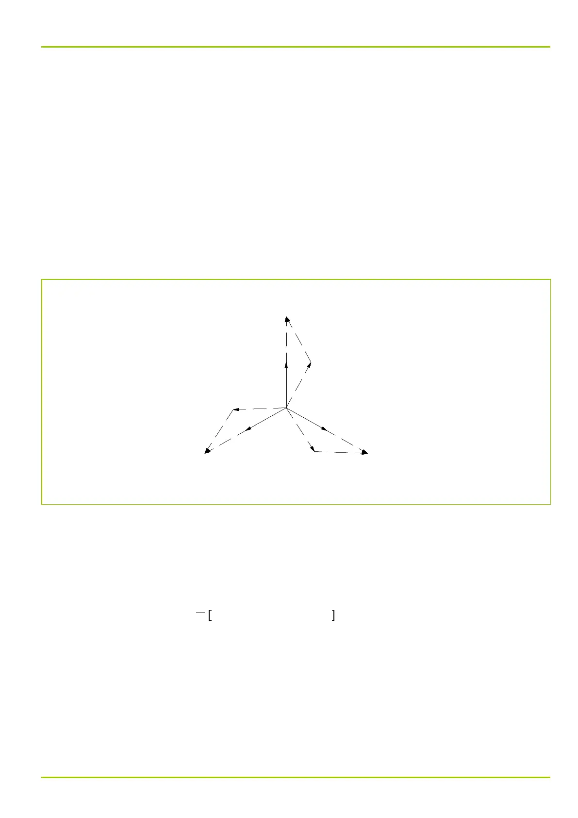
matching. In Fig. 3-80, (p. 3-113), such a vector diagram is depicted for a
transformer having the vector group Yd5 as an example. By subtraction of each
phase current from the cyclically leading phase current and subsequent
multiplication by the factor 1/√3, the desired matching is achieved.
Q6Z0105A
-Iam,B,b
-Iam,C,b
√3⋅Is,2,b
√3⋅Is,3,b
-Iam,A,b
√3⋅Is,1,b
Iam,A,b
Iam,B,b
Iam,C,b
Is,3,a
Is,2,a
Is,1,a
Fig. 3-80: Vector diagram for vector group matching with a transformer having the vector group Yd5
3.21.4 Zero-sequence Current Filtering
Table 3-1, (p. 3-114) shows that the zero-sequence current is subtracted from
the phase currents of winding a and, for all even vector groups, from the phase
currents of winding b. According to the theory of symmetric components, the
zero-sequence current is calculated as follows:
I
am,0,z
=
1
3
. I
am,A,z
+ I
am,B,z
+ I
am,C,z
z: end a or b
I
am
: amplitude-matched current
Zero-sequence filtering may be disabled separately for each end.
In general this disabling of zero-sequence filtering is intended for even-numbered
vector groups. Should the side considered here require the setting of an odd-
numbered vector group while at the same time no operational system star point
grounding is provided within the protected area, then, in view of increased
sensitivity with single-pole internal faults, it is recommended that the respective
zero-sequence current is fed to the individual measuring systems again.
3 Operation
P631
P631/EN M/R-11-C // P631-310-650 3-113