IA,a
IA,a
IA,a
Ineg/Ipos
c
MCM_1:
Ineg/Ipos> PSx
[ * ]
c
c
MCM_1:
Enabled
[ 036 194 ]
MAIN:
Phase sequence
[ 010 049 ]
MCM_1:
Blocking EXT
[ 036 213 ]
>0.02 Inom
>0.02 Inom
Ineg
Ipos
5s
0
c
MCM_1:
Operate delay PSx
[ * ]
SFMON:
Meas. c. I faulty, a
[ 091 026 ]
64Z5187B
MCM_1:
Meas. circ. I faulty
[ 036 198 ]
MCM_1:
Starting
[ 036 212 ]
Parameter
set 1
set 2
set 3
set 4
MCM_1:
Operate delay PSx
081 046
082 046
083 046
084 046
MCM_1:
Ineg/Ipos> PSx
081 042
082 042
083 042
084 042
≥1
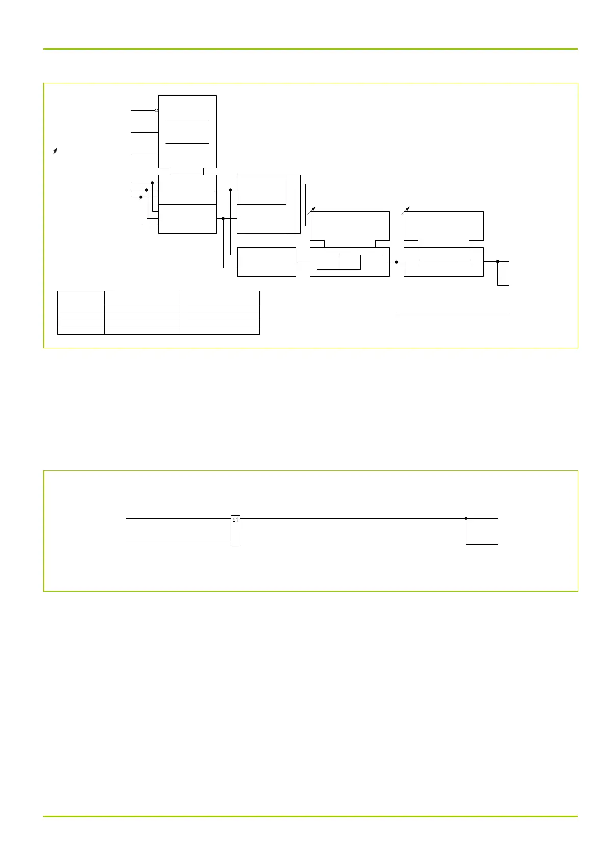
Fig. 3-124: Measuring-circuit monitoring for end a
3.26.3 Multiple Signaling from the Measuring-Circuit Monitoring
Function
The signals issued by the measuring-circuit monitoring function (and/or current
transformer supervision, see Section 3.25, (p. 3-151)) are grouped to form the
MAIN: Meas. circ.I faulty multiple signal. A signal is simultaneously issued by
the self-monitoring function.
62Z5185A
MAIN:
Meas. circ.I faulty
[ 036 155 ]
MCM_1:
Meas. circ. I faulty
[ 036 198 ]
SFMON:
Meas. circ. I faulty
[ 091 018 ]
MCM_2:
Meas. circ. I faulty
[ 036 199 ]
Fig. 3-125: Signals issued by the measuring-circuit monitoring function
3 Operation
P631
P631/EN M/R-11-C // P631-310-650 3-157