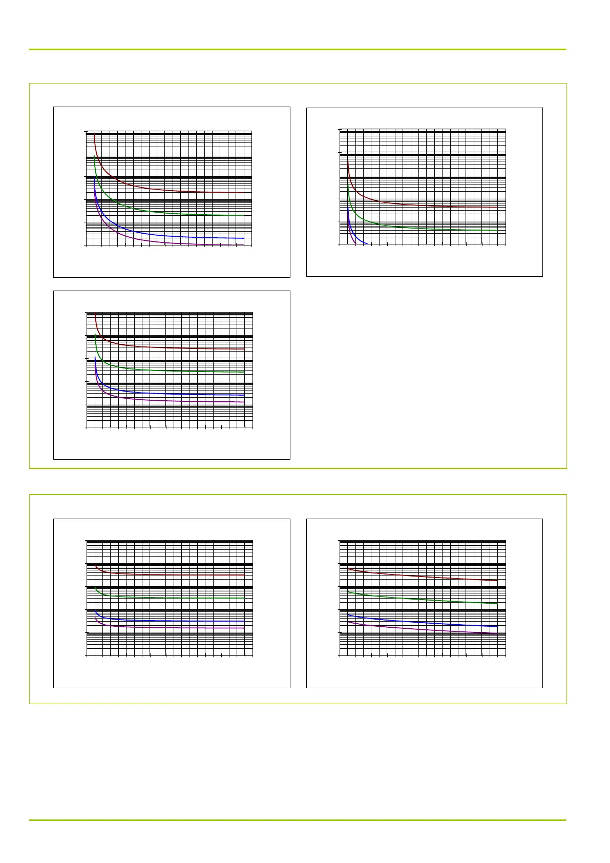
IDMT Tripping Characteristics per ANSI
I/Iref
t/s
k=0.05
k=0.1
k=1
k
=
10
0.01
0.1
1
10
100
1000
0 1 2 3 4 5 6 7 8 9 10 11 12 13 14 15 16 17 18 19 20 21
I/Iref
t/s
k
=
0.05
k
=
0.1
k
=
1
k
=
10
0.01
0.1
1
10
100
1000
0 1 2 3 4 5 6 7 8 9 10 11 12 13 14 15 16 17 18 19 20 21
I/Iref
t/s
k
=
0.05
k
=
0.1
k
=
1
k
=
10
Characteristic 8: ANSI, Normally Inverse
0.01
0.1
1
10
100
1000
0 1 2 3 4 5 6 7 8 9 10 11 12 13 14 15 16 17 18 19 20 21
Characteristic 9: ANSI, Short Time Inverse
Characteristic 10: ANSI, Long Time Inverse
Fig. 3-101: Tripping characteristics as per ANSI.
IDMT Tripping Characteristics, RI-Type Inverse and RXIDG-Type Inverse
Characteristic 11: RI-Type Inverse
0.01
0.1
1
10
100
1000
0 1 2 3 4 5 6 7 8 9 10 11 12 13 14 15 16 17 18 19 20 21
I/Iref
t/s
k
=
0.05
k
=
0.1
k
=
1
k
=
10
0.01
0.1
1
10
100
1000
0 1 2 3 4 5 6 7 8 9 10 11 12 13 14 15 16 17 18 19 20 21
I/Iref
t/s
k
=
0.05
k
=
0.1
k
=
1
k
=
10
Characteristic 12: RXIDG-Type Inverse
Fig. 3-102: RI-type inverse and RXIDG‑type inverse tripping characteristics.
3.23.3 Phase Current Stage
The three phase currents are monitored by the P631 to detect when they exceed
the set thresholds. Alternatively, two different thresholds can be active. The
“dynamic” threshold is active for the set hold time of the “dynamic parameters”
(see Section 3.12.5, (p. 3-76)); the “normal” threshold is active when no hold
P631
3 Operation
3-136 P631/EN M/R-11-C // P631-310-650