5.6.1.4 Connecting a Resistance Thermometer
A resistance thermometer can be connected if the device is fitted with analog
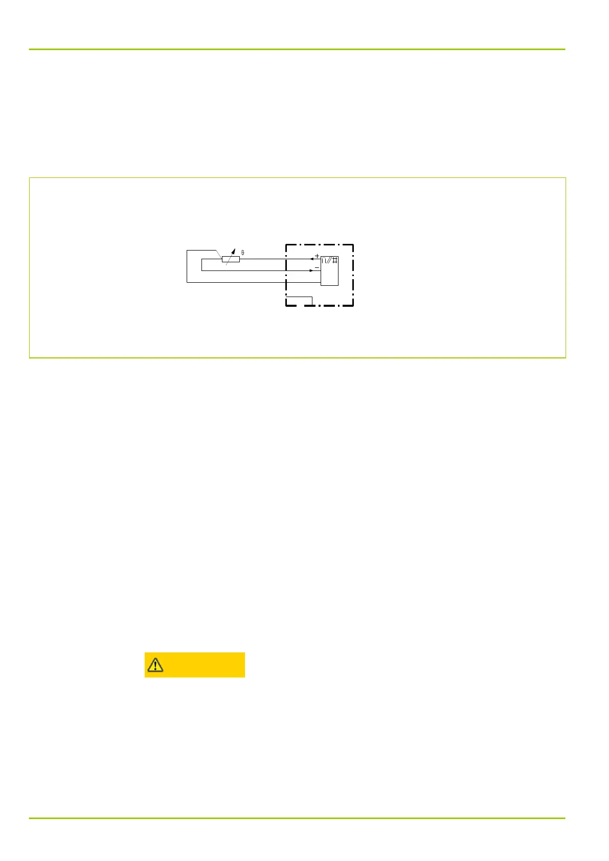
module Y. This analog I/O module input is designed to connect a PT 100
resistance thermometer. The PT 100 should be connected using the 3-wire
method (see Fig. 5-10, (p. 5-14)). No supply conductor compensation is
required in this case.
S8Z52H9A
PT 100
P631
Fig. 5-10: Connecting a PT 100 using the 3-wire method.
5.6.1.5 Connecting Binary Inputs and Output Relays
The binary inputs and output relays are freely configurable. When configuring
these components it is important to note that the contact rating of the binary I/O
modules (X) varies (see Section 2.5.7, (p. 2-13)).
The polarity for connected binary signal inputs is to be found in the terminal
connection diagrams (see supporting documents supplied with the device or in
Section 5.7, (p. 5-18)). This is to be understood as a recommendation only.
Connection to binary inputs can be made as desired.
5.6.2 Connecting the IRIG‑B Interface
An IRIG‑B interface for time synchronization may be installed as an optional
feature. It is connected by a BNC connector. A coaxial cable having a
characteristic impedance of 50 Ω must be used as the connecting cable.
5.6.3 Connecting the Serial Interfaces
5.6.3.1 PC Interface
The PC interface is provided so that personnel can operate the device from a
personal computer (PC).
Warning!
⚫
The PC interface is not designed as a permanent connection. Consequently,
the female connector does not have the extra insulation from circuits
connected to the system that is required per VDE 0106, part 101.
5.6.3.2 Communication Interfaces
The communication interfaces are provided as a permanent connection of the
device to a control system for substations or to a central substation unit.
Depending on the type, communication interface 1 on the device is connected
P631
5 Installation and Connection
5-14 P631/EN M/R-11-C // P631-310-650