7.1.3 Function Parameters
7.1.3.1 Global
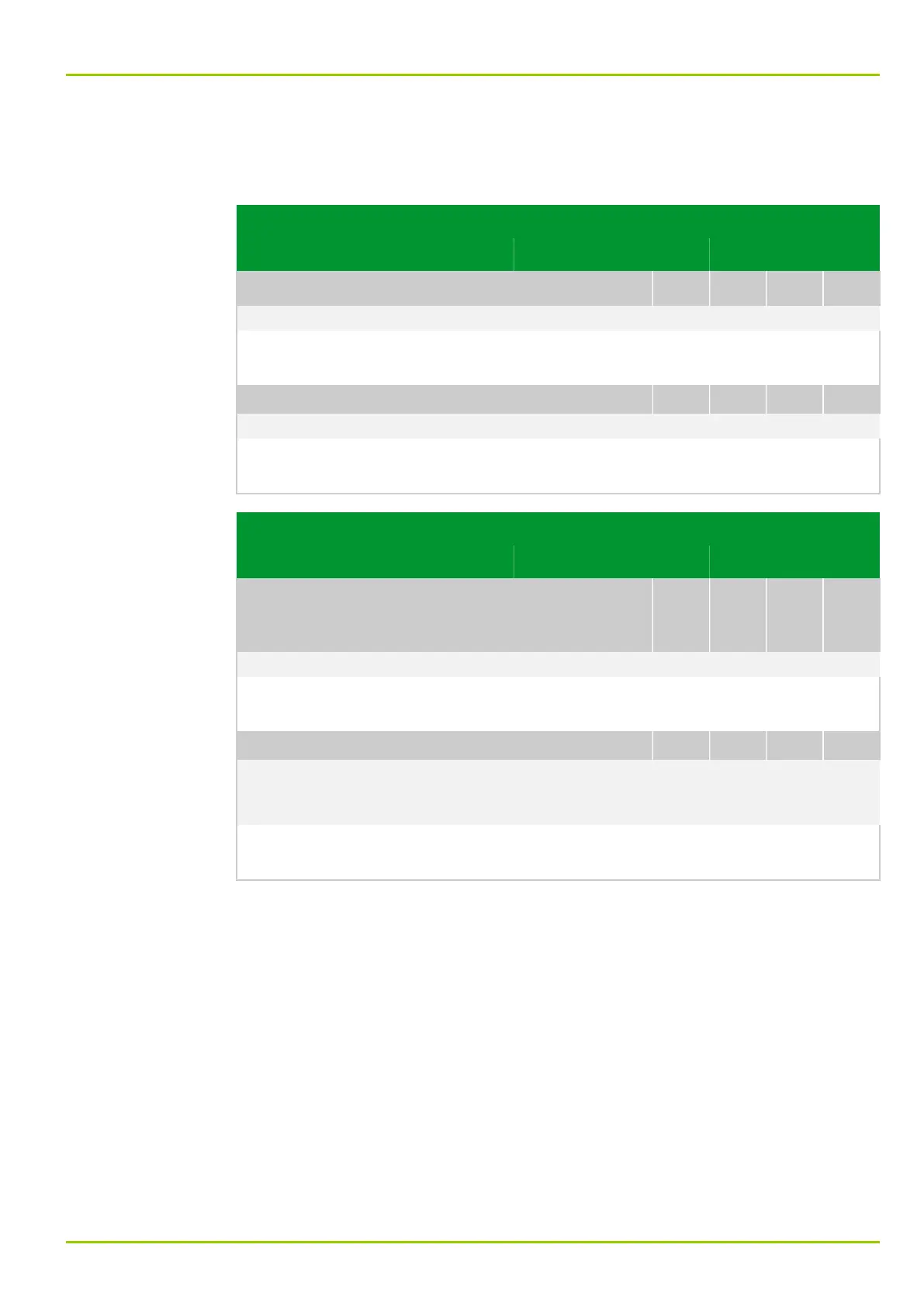
Parameter Address
Default Min Max Unit Logic Diagram
PC link
PC: Command blocking
003 182
0: No Fig. 3-5, (p. 3-9)
[spacer]
When command blocking is activated, commands are rejected at the PC
interface.
[spacer]
PC: Sig./meas.val.block.
003 086
0: No Fig. 3-5, (p. 3-9)
[spacer]
When signal and measured value blocking is activated, no signals or measured
data are transmitted through the PC interface.
Parameter Address
Default Min Max Unit Logic Diagram
“Logical”
communication
interface 1
COMM1: Command block. USER
003 172
1: Yes Fig. 3-6, (p. 3-11)
[spacer]
When command blocking is activated, commands are rejected at communication
interface 1.
[spacer]
COMM1: Sig./meas.block.USER
003 076
0: No Fig. 3-7, (p. 3-12)
Fig. 3-8, (p. 3-13)
Fig. 3-9, (p. 3-14)
[spacer]
When signal and measured value blocking user is activated, no signals or
measured data are transmitted through communication interface COMM1.
7 Settings
P631
P631/EN M/R-11-C // P631-310-650 7-71