19Z80CDA
LOG_2:
Output 1
[ 052 032 ]
LOG_2:
Output 1 (t)
[ 052 033 ]
LOG_2:
Enabled
[ 011 138 ]
LOG_2:
Op. mode t output 1
[ 050 001 ]
0: No
0
1
2
3
4
5
0
5
1: Oper./releas.delay
2: Oper.del./puls.dur.
3: Op./rel.delay,retrig
4: Op.del./puls.dur.,rt
5: Minimum time
LOG_2:
Time t1 output 1
[ 050 002 ]
LOG_2:
Time t2 output 1
[ 050 003 ]
LOG_2:
Fct.assignm. outp. 1
[ 050 000 ]
LOG_2:
General enable USER
[ 011 137 ]
1: Yes
MAIN:
Protection active
306 001
Signal 1
Signal 2
Signal 3
Signal n
0
1
0: Without timer stage
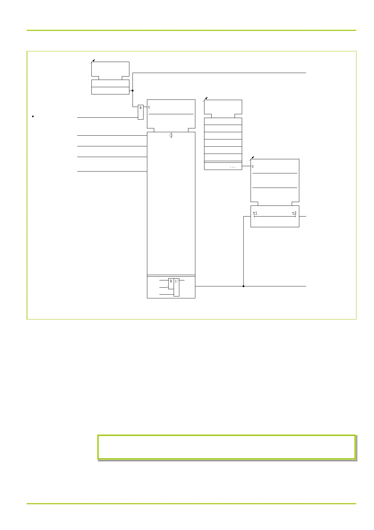
Fig. 3-142: Setting options for programmable logic, function group LOG_2 (shown here for output 1).
The output signal of an equation can be fed into a further, higher order, equation
as an input signal thus creating a sequence of interlinked Boolean equations. The
equations are processed in the sequence defined by the order of each equation.
It should be noted that in the case of overlapping equations, the result is
provided by the equation with the highest order.
The output signal of each equation is fed to a separate timer stage with two
timer elements and a choice of operating modes. This offers the possibility of
assigning a freely configurable time characteristic to the output signal of each
Boolean equation. In the Minimum time operating mode, the setting of timer
stage t2 has no effect. The following diagrams (Fig. 3-143, (p. 3-176) to
Fig. 3-147, (p. 3-178)) show the time characteristics for the various timer stage
operating modes.
If the P631 is switched to offline the equations are not processed and all outputs
are set to the “0” logic level.
3 Operation
P631
P631/EN M/R-11-C // P631-310-650 3-175