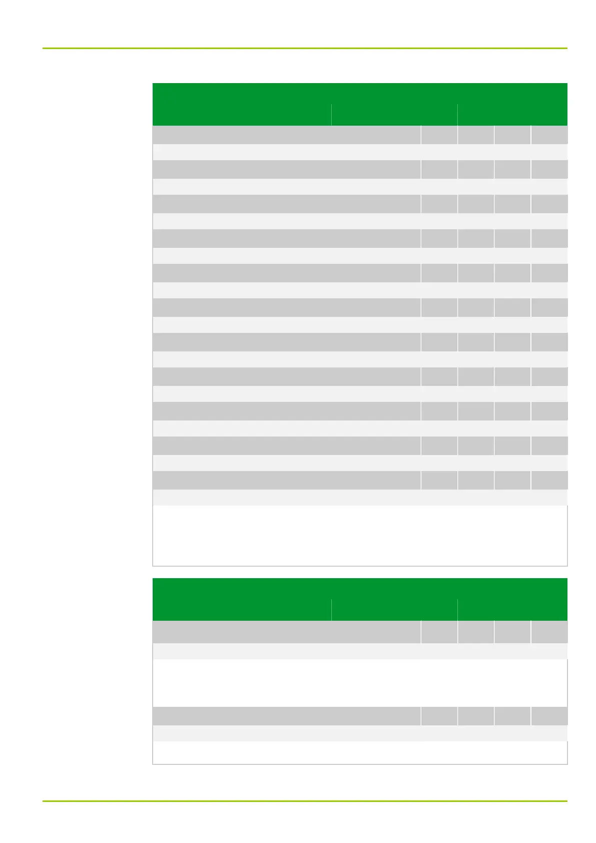
Parameter Address
Default Min Max Unit Logic Diagram
[spacer]
GSSE: Input 22 fct.assig.
105 109
061 000: MAIN: Without function
[spacer]
GSSE: Input 23 fct.assig.
105 114
061 000: MAIN: Without function
[spacer]
GSSE: Input 24 fct.assig.
105 119
061 000: MAIN: Without function
[spacer]
GSSE: Input 25 fct.assig.
105 124
061 000: MAIN: Without function
[spacer]
GSSE: Input 26 fct.assig.
105 129
061 000: MAIN: Without function
[spacer]
GSSE: Input 27 fct.assig.
105 134
061 000: MAIN: Without function
[spacer]
GSSE: Input 28 fct.assig.
105 139
061 000: MAIN: Without function
[spacer]
GSSE: Input 29 fct.assig.
105 144
061 000: MAIN: Without function
[spacer]
GSSE: Input 30 fct.assig.
105 149
061 000: MAIN: Without function
[spacer]
GSSE: Input 31 fct.assig.
105 154
061 000: MAIN: Without function
[spacer]
GSSE: Input 32 fct.assig.
105 159
061 000: MAIN: Without function
[spacer]
Function assignment of the virtual GSSE input to a binary logical state signal on
the device (IED) so that it can be processed further by the protection or logic
functions. The signal configured at this point will receive the state of the bit
pair, as configured above, and which was received with GSSE.
Parameter Address
Default Min Max Unit Logic Diagram
IRIG‑B interface
IRIGB: Function group IRIGB
056 072
0: Without
[spacer]
Cancelling function group IRIGB or including it in the configuration. If the
function group is cancelled from the configuration, then all associated settings
and signals are hidden.
[spacer]
IRIGB: General enable USER
023 200
0: No Fig. 3-20, (p. 3-33)
[spacer]
Disabling or enabling the IRIG-B interface.
7 Settings
P631
P631/EN M/R-11-C // P631-310-650 7-49