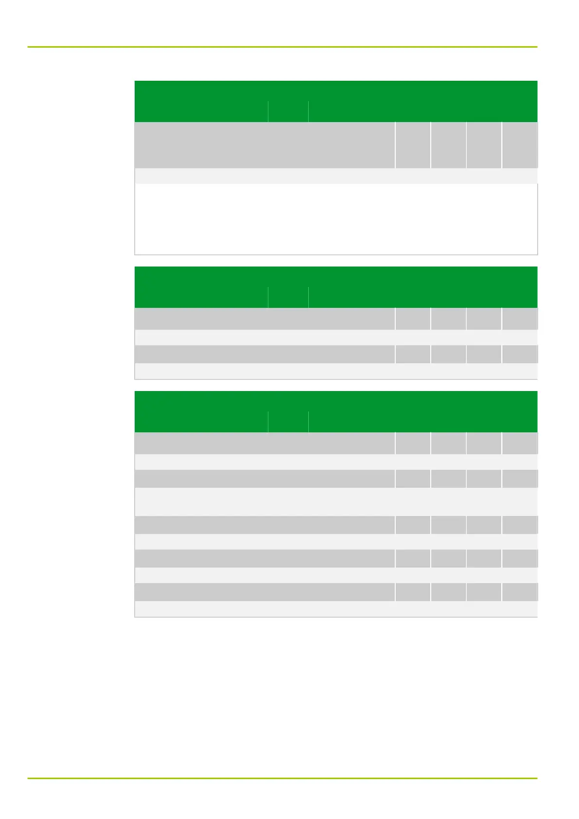
Parameter Address
Default Min Max Unit Logic Diagram
IEC Generic
Substation Status
Events
GSSE: IED link faulty
105 181
0: No
[spacer]
Display which appears as soon as receipt of at least one of the configured
GOOSEs is faulty or not available. To each GOOSE the GOOSE sending device
will attach a validity stamp, up to which a repetition of GOOSE will be carried out
independent of a change of state. Thus the unit monitors the time period at
which the next state signal must be received.
Parameter Address
Default Min Max Unit Logic Diagram
IRIG‑B interface
IRIGB: Enabled
023 201
0: No Fig. 3-20, (p. 3-33)
[spacer]
IRIGB: Synchron. ready
023 202
0: No Fig. 3-20, (p. 3-33)
Parameter Address
Default Min Max Unit Logic Diagram
Measured data input
MEASI: Reset Tmax EXT
006 076
0: No
[spacer]
MEASI: Enabled
035 008
0: No Fig. 3-23, (p. 3-38)
Fig. 3-31, (p. 3-47)
[spacer]
MEASI: PT100 faulty
040 190
0: No Fig. 3-28, (p. 3-43)
[spacer]
MEASI: Overload 20mA input
040 191
0: No Fig. 3-26, (p. 3-41)
[spacer]
MEASI: Open circ. 20mA inp.
040 192
0: No Fig. 3-26, (p. 3-41)
P631
8 Information and Control Functions
8-38 P631/EN M/R-11-C // P631-310-650