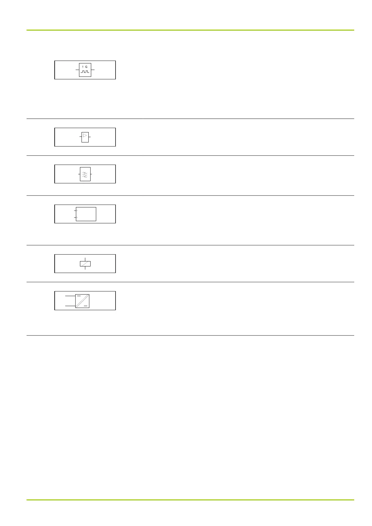
Non-stable flip-flop
When the input variable changes to 1, a pulse sequence is
generated at the output.
The ! to the left of the G indicates that the pulse sequence starts
with the input variable transition (synchronized start).
If there is a ! to the right of the G, the pulse sequence ends with
the ending of the 1 signal at the input (synchronized stop).
Amplifier
The output variable is 1 only if the input variable is also 1.
Band pass filter
The output only transmits the 50 Hz component of the input
signals. All other frequencies (above and below 50 Hz) are
attenuated.
Counter
At the + input the input variable transitions from 0 to 1 are
counted and stored in the function block.
At the R(eset) input a transition of the input variable from 0 to 1
resets the counter to 0.
Electromechanical drive in general, here a relay, for example.
Signal level converter
with electrical isolation between input and output.
L+ = pos. voltage input
L− = neg. voltage input
U1 = device identifier
A3 Glossary
P631
P631/EN M/R-11-C // P631-310-650 A3-5