Page 12
Measure
optoCONTROL 2600
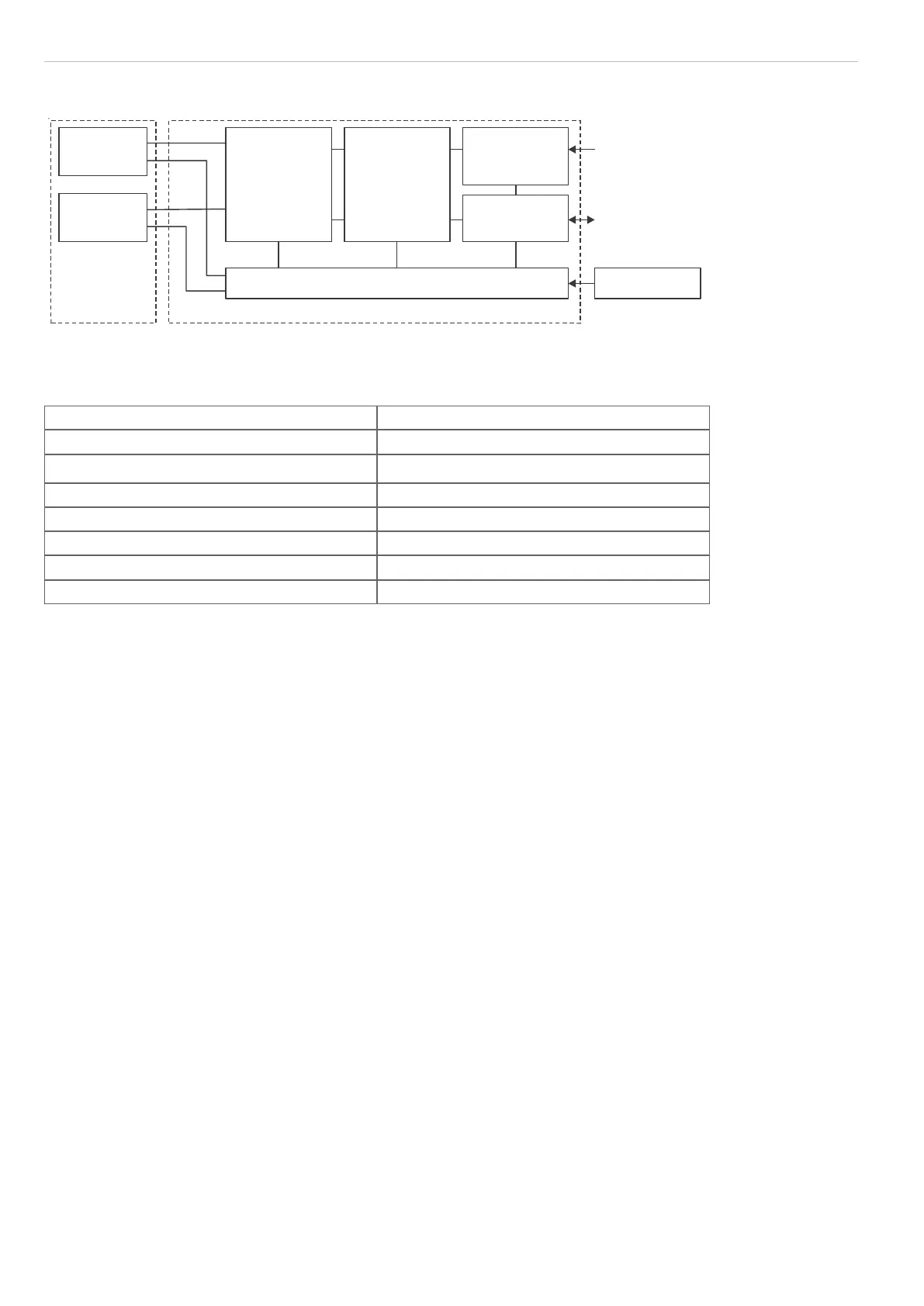
3.6 Block Diagram
Light source
(LED)
Receiver
(Camera)
Sensor signal
processing
(digital signal
processor)
Communica-
tion unit
(Controller)
Display and
operation unit
Inputs and
outputs
Power supply
User
Process
+24 VDC
Sensor SU Controller
Fig. 7 Block diagram of the ODC 2600 measuring system
3.7 Analog Output
Output voltage (without offset) 0 ... +10 V DC
Max. output range (with offset, factor) -10.0 V ... +10.0 V DC
Output span (100 % of measurement range) U
OUT
10.0 V DC
Output voltage (with error indication) -10.04 V ... +10.04 V DC
Internal resistance 100 Ohm
Minimum load resistance 1 kOhm
Recommended load resistance 1 MOhm
Maximum capacitive load, see 6.4 47 nF
3.8 Input Zero Point / RESET
By briefly connecting (0.5 to 3 s) together the inputs “Zero point” (Signal and GND) during measurement, the mea-
surement is set to the default master value, see 6.3.7.2. If a master value has not yet been entered, the measurement
is set to 00.000 during zero setting.
If the zero point input is activated for between 3 and 6 s (closed), resetting occurs to the measurement without mas-
ters or zeros. Pulses which are shorter than 0.5 s or longer than 6 s are not processed.
The zero point input is only active in the normal measurement mode with valid measurements. In the TRIGGER mea-
surement mode this input is used as RESET and therefore no zero setting is possible.
In the Multi-segment operating mode and with erroneous measurements, no zero setting is possible. The input
Zero point affects the display and the analog output only. The digital output is not affected.
i
Zero-setting input on the 25-pole connector:
Pin 5: Signal
Pin 18: GND
i
The zero point input only affects the display and the analog output. The digital output is not affected.
3.9 Synchronization
If two or more optoCONTROL 2600s are operated on the same target, they can be synchronized to one another, see
6.5.
As master, controller 1 then synchronizes controller 2.
All synchronization signals are electrically isolated by optocouplers.
 Loading...