Page 13
Measure
optoCONTROL 2600
3.10 Error Output
If an error is detected by the measurement system (e.g. no target present, too much
extraneous light, etc.), then the switching output Error becomes conducting.
The error output always refers to the unaveraged measurements (at a rate of 2.3 kHz).
The red light emitting diode (Error LED) also indicates the error.
For more details, see 5.6.
i
The error output is provided on the 25-pole connector.
Pin 1: Error output
Pin 14: GND
3.11 Light Source Control and Trigger Input
In the menu options you can also activate the switching input for the external light
source control light source off. The light source is then active (light on) when the
input is short-circuited.
In the triggered measurement mode, see 6.3.7.8, this input is used as a trigger input. The
light source can not then be switched off externally.
Activating the switch input for the light source controller automatically switches the sys-
tem to normal operation (untriggered). This has a higher priority than triggering.
The system is delivered with the input not activated, meaning that nothing has to be con-
nected to the 25-pole D Sub to put the system into operation.
i
The activation of the input as light source control resets to normal operation.
The light source control has a maximum switching frequency of 10 Hz.
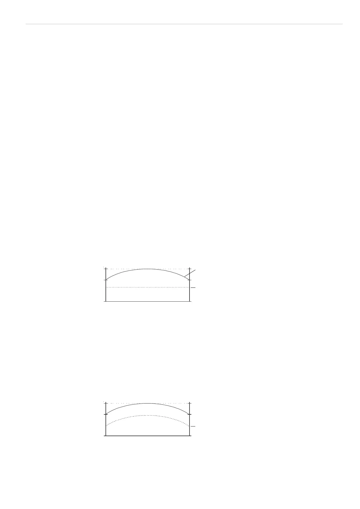
3.12 Edge Detection Threshold for Transparent Measurement Objects
The system’s fixed edge detection threshold of the video signal across the entire mea-
surement range is defaulted at 50 %.
Video image with fixed edge detection threshold
Fixed edge detection threshold: 50 %
Fig. 8 Video image with fixed edge detection threshold
i
There must be no light threshold when measuring object in the beam path.
In the case of highly transparent objects only a very small amount of the light will be
blocked. If the edge detection threshold is set too low the measurement object will not
be detected. The edge detection threshold can be adjusted to any setting between 20 %
and 90 % in 1 % increments, see A 5.4, menu item 1B10 – Choose threshold val-
ue for dark/light transition.
A very high edge detection threshold will require a dynamic curved edge detection
threshold. This can be set by activating the 1B20 – Set light referencing tun-
ing menu item.
Dynamic edge detection threshold: 50 %
Fig. 9 Video image with dynamic edge detection threshold

 Loading...
