Page 10
Measure
optoCONTROL 2600
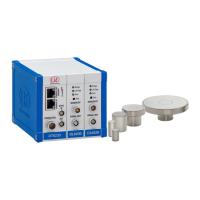
3.3.2 Rear View of the Controller
Receiver (12-pole) Inputs and outputs (25-pole)
Light source (5-pole)
Supply voltage (3-pole)
Fig. 5 Connection on the rear side of the controller
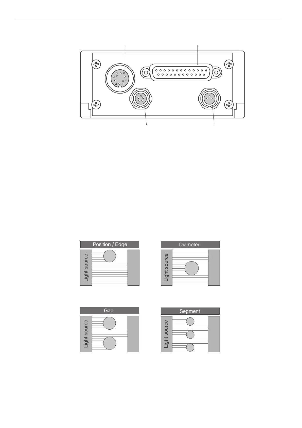
3.4 Operating Modes
The following operating modes are selectable via a menu-assisted selection (measure-
ment program, see 6.3.6):
- Position of an edge (bright/dark or dark/bright)
- Diameter of a target
- Gap between two targets
- Distance between two selectable edges (segment)
- Serial measurement of up to four freely selectable segments (multi-segment) via the
digital output (e.g. segments 1 - 4 and 2 - 3)
i
Factory setting:
Position edge bright - dark
Receiver
Receiver
Receiver
Receiver
1
2
3
4
Fig. 6 Methods of operation
For each measurement program 2 limits and 2 warning levels can be programmed. For
the Multi-segment program only 2 limits per segment 1 and segment 2 can be pro-
grammed.
Potentially measured segments 3 and 4 are not monitored.
Application-specific measurement programs can also be generated by menu.
 Loading...