Page 57
Measure
optoCONTROL 2600
6.7 Timing
The controller in the ODC 2600 operates internally in 5 cycles:
1. Integration: Gathering of the incoming light in the receiver (measurement).
2. Reading in: Conversion and saving of the light signals as digital values.
3. Computation: Measurement determination in the DSP (digital signal processor).
4. Controlling: Transfer of the measurements to the output controller where statistical
computations (Segment, Min, Max, PtP, Limits, Zero-setting)
5. Output: Output via the analog and digital interfaces, activation of limit switching
functions.
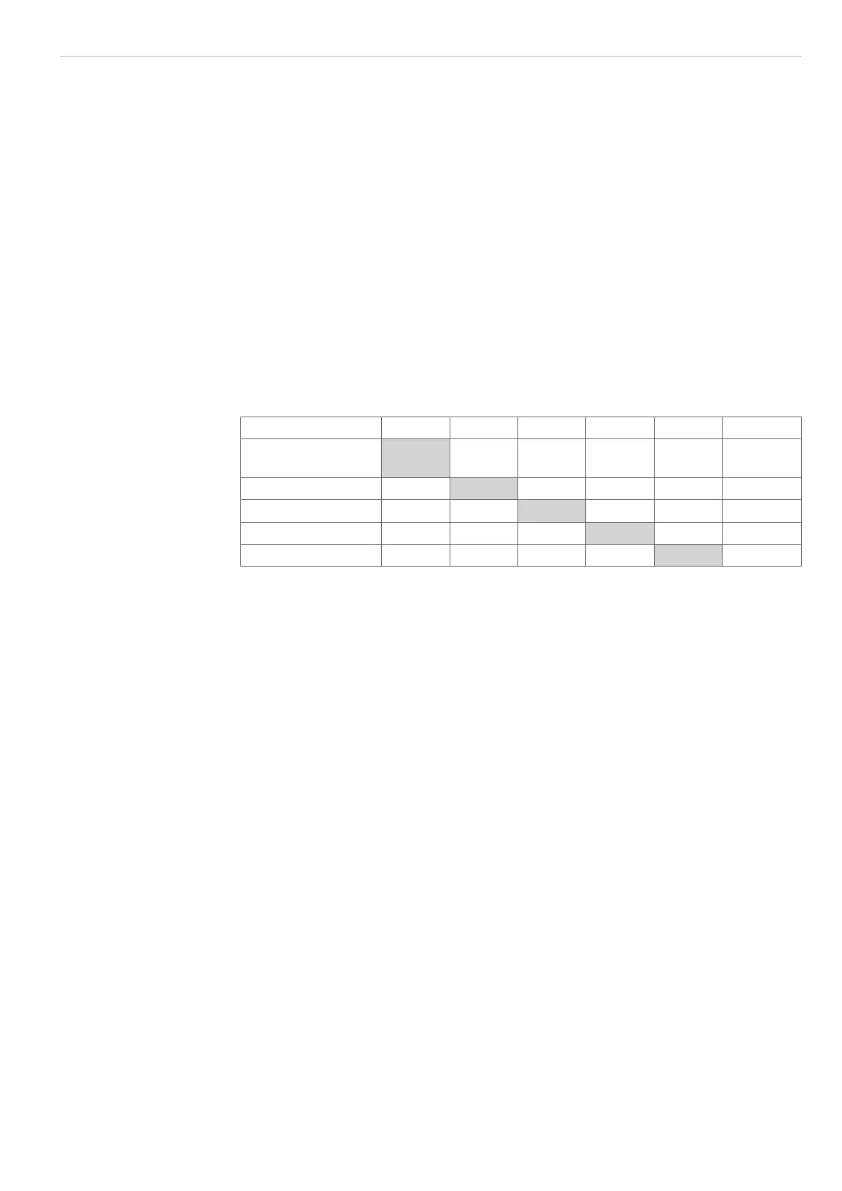
Each cycle takes about 435 µs (1 / measuring rate). After 5 cycles in each case the
measured value N is available on the output. The delay between the input reaction and
output signal is 2175 µs. The processing of the cycles occurs sequentially in time and
parallel in space, see Fig. 52. After a further 435 µs the next measurement N + 1 is pres-
ent on the output.
One output cycle is added for each segment in Multi-segment mode. This reduces
the measuring rate.
Cycle 1. 2. 3. 4. 5. Time (µs)
Integration
(measurement)
N N+1 N+2 N+3 N+4 435
Reading in N-1 N N+1 N+2 N+3 870
Computation N-2 N-1 N N+1 N+2 1305
Controlling N-3 N-2 N-1 N N+1 1740
Output N-4 N-3 N-2 N-1 N 2175
Fig. 52 Internal cycles in the ODC controller

 Loading...
