Page 58
Measure
optoCONTROL 2600
6.8 Error Effects
6.8.1 Error Effects on the Light Beam
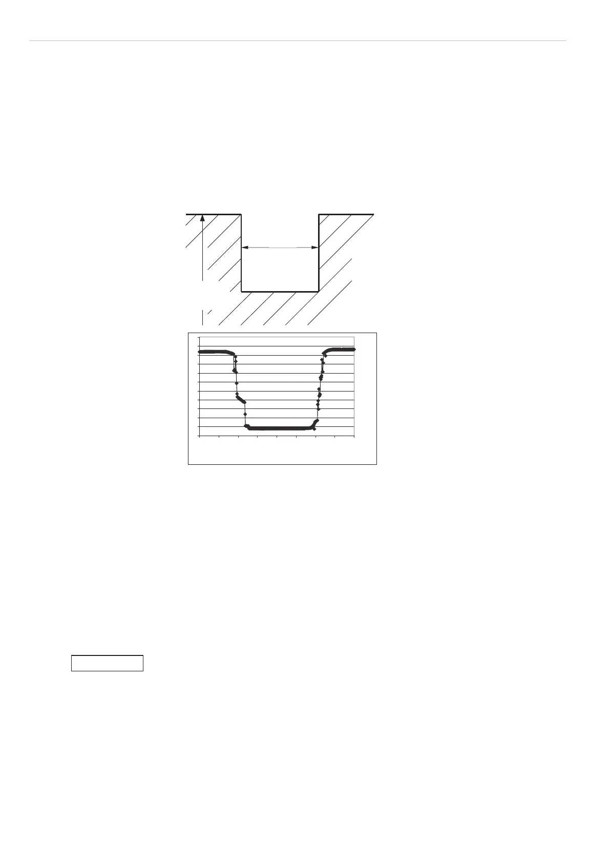
Edge changes cause, as can be seen in the illustration, see Fig. 53, measurement errors
over a width of approx. 0.05 mm.
Therefore measurements should not be carried out in the immediate vicinity of a sudden
change (e.g. recesses, shoulders, etc.).
If edges, which are not used in the measurement process, protrude into the light beam,
then they should be taken into account during the editing of the measurement program
(masked out). To do this, use the program Segment. Then you can freely select between
which edges the measurement is to be taken.
Edge change (recess
in target object)
Output signal of the
ODC 2600
0,05 0,1 0,15 0,2 0,25 0,3 0,35 0,4 0,45
mm
0.3 mm
Edge
measurement
Region with measurement errors approx. 0.05 mm wide
Fig. 53 Effects on the light beam due to edge changes
6.8.2 Extraneous Light
The telecentric objective lens in the receiver only allows beams onto the CCD array
which are precisely parallel to the optical axis.
Such a beam can be generated by a self-illuminated measurement object or by the
directed reflection of extraneous light on shiny target objects.
The video signal image on the display can be used for observation.
The red filter in the receiver blocks radiation below 610 nm wavelength (visible light).
The direct irradiation from primary light sources, such as for example, reflector lamps or
sunlight, onto the receiver and the target should be avoided.
Avoid direct irradiation of ambient light in the receiving area.
> Measurement error or measurement is not possible
NOTICE

 Loading...
