Page 36
Measure
optoCONTROL 2600
6.4 Analog Output
6.4.1 Setup
Setup occurs specific to the measurement program in the menu Edit program:
> Enter gain for analog output or Enter gain for analog output.
6.4.2 Measurement Conversion
The measurement value (MV) is calculated from the analog output voltage as follows:
4.0
MV (mm) (V
OUT
- Analog offset)
Analog gain
Value ranges
Analog offset: -50.0000 V ... +50.0000 V
Analog gain: -4.00000 ... +4.00000
The analog output voltage to be expected for a certain measurement value can be calcu-
lated from the following formula:
MV (mm)
V
OUT
(V) *Analog gain + Analog offset
4.0
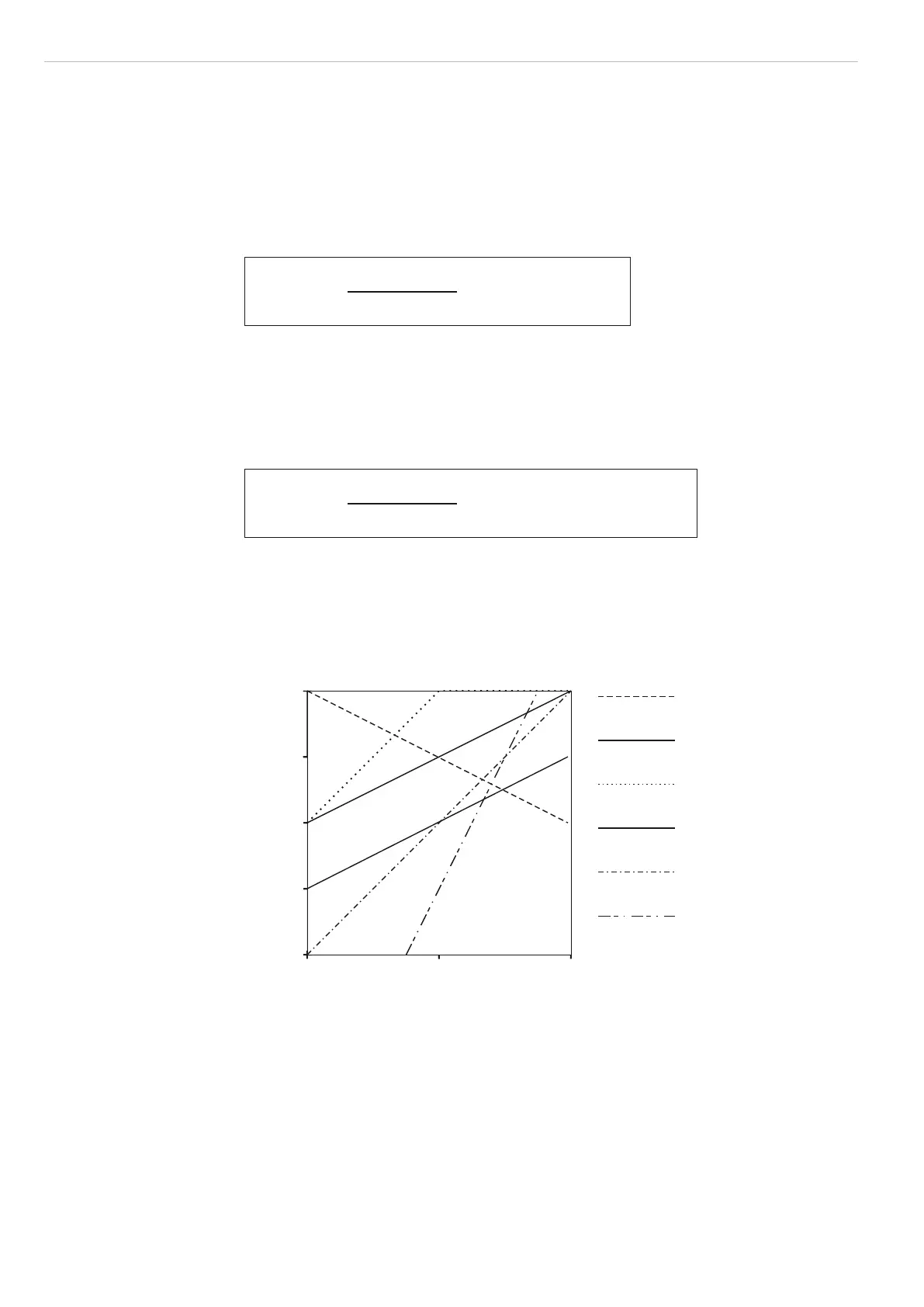
With the two quantities, analog gain and analog offset, you can produce all the arising
linear output characteristics as shown in the following graph. This is particularly interest-
ing for adaptation to evaluation equipment with lower resolution or lower voltage span on
the input. In this respect, the above formula is changed according to the analog gain.
Then it is possible, for example, to extend a measurement span of 10 mm to a voltage
span of 10 V; the analog gain in this case is +4.0.
10
5
0
-5
-10
AF Analog gain
AO Analog offset
Output voltage in VDC
0 20 40
x in mm
AF -1, AO 10 V
AF 1, AO 0 V
AF 2, AO 0 V
AF 1, AO -5 V
AF 2, AO -10 V
AF 4, AO -25 V
Fig. 38 Analog scaling of output characteristics
i
Zero-setting, see 6.3.7.1 and mastering, see 6.3.7.2 also affect the analog output.
It should therefore be carried out before the analog gain is changed.
The output voltage has an overrun respectively underrun of 20 mV (0.068 mm). This
means it can exceed resp. undercut the zero point and the full scale (+10 VDC) by
20 mV in each case.
In the above example with AG 2 and AO 0 V the output voltage from an edge position x
> 20 mm is limited to 10.02 V. With x > 40,.... mm the error value of 10.04 V then ap-
pears.
If negative output voltages disturb, an analog offset of -20 mV (-0.020 V) can be entered.
With Error in the standard setting, a voltage of +10.04 V is output.

 Loading...
