Page 19
Measure
optoCONTROL 2600
5.4 Power Supply
The supply voltage is preferably connected via a screened two-core cable, e.g. via the
supply cable PC2500-3. Route the cable screen to a potential equalization terminal in
the vicinity of the power supply unit. The supply voltage of ODC2600 devices is internally
protected against reverse polarity.
i
Please use the power supply unit for measurement instruments only and not for
drive units or similar sources of pulse interference at the same time.
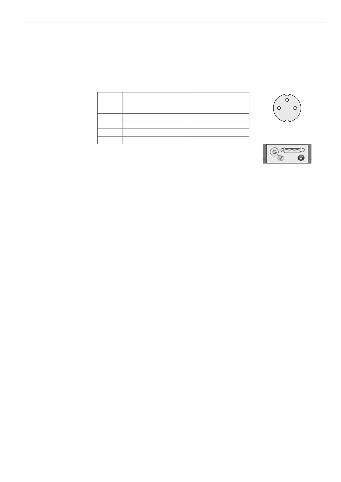
Pin Signal Conductor coloring
PC2500,
old version in ( )
1
2
3
3-pole male cable connector,
view on solder pin side
1 GND supply voltage black (blue or brown)
2 N.C. ----
3 +24 VDC (±15 %), <1 A red (white)
Housing Cable screen tin-plated
Fig. 18 Pin assignment, round connector (type Binder),
3-pole
Minimum bending radiuses of the connecting cables are 20 mm.
5.5 Connecting an Analog Terminal Device
i
For connecting an analog terminal device use either the analog connecting cable
SCA2500-x, SCD2500-3/10/RS422 or SCD2500-3/3/RS232, see A 1, or your own
screened cable.
When using the connecting cable SCA2500-x, see A 1, the outer screen must be con-
nected to the receiver screen (e.g. plug housing).
The inner screen acts as the signal return conductor (analog ground AGND) and must
be connected to the receiver ground. This screen should not have any connection to the
housing screen (plug housing).
When using your own cable, a single-core screened cable is recommended, the screen
of which is used as the signal return conductor (analog ground AGND). This screen must
not have any connection to the housing screen (plug housing) and the receiver screen.
i
In the case of interference try connecting the outer screen to the receiver screen
with a ceramic capacitor of 10 to 100 nF or not connecting it at all.
A capacitor of up to 47 nF can be wired in parallel to the input of the evaluation device
to counter any high frequencies and pulse-shaped parasitic interference on the analog
signal.
Route the analog connecting cable according to the general applicable rules in mea-
surement engineering, i.e. for example, not directly next to pulse-loaded lines, best in a
separate cable duct.

 Loading...
