Page 39
Measure
optoCONTROL 2600
6.6 Digital Interfaces
6.6.1 Interface Parameters
Factory setting: RS232, 115.2 kBaud
Only one digital interface is available (RS422 or RS232). It is activated by selecting in the menu Select options >
Select active interface and configured in the menu Select RS232 parameters (or RS422).
The data word (one measurement) is composed of three consecutive bytes (L-byte, M-byte, H-byte).
The maximum measuring rate of the measurement system is only obtained with a baud rate of 115.2 kBaud or higher.
With slower data transfer measurements are omitted.
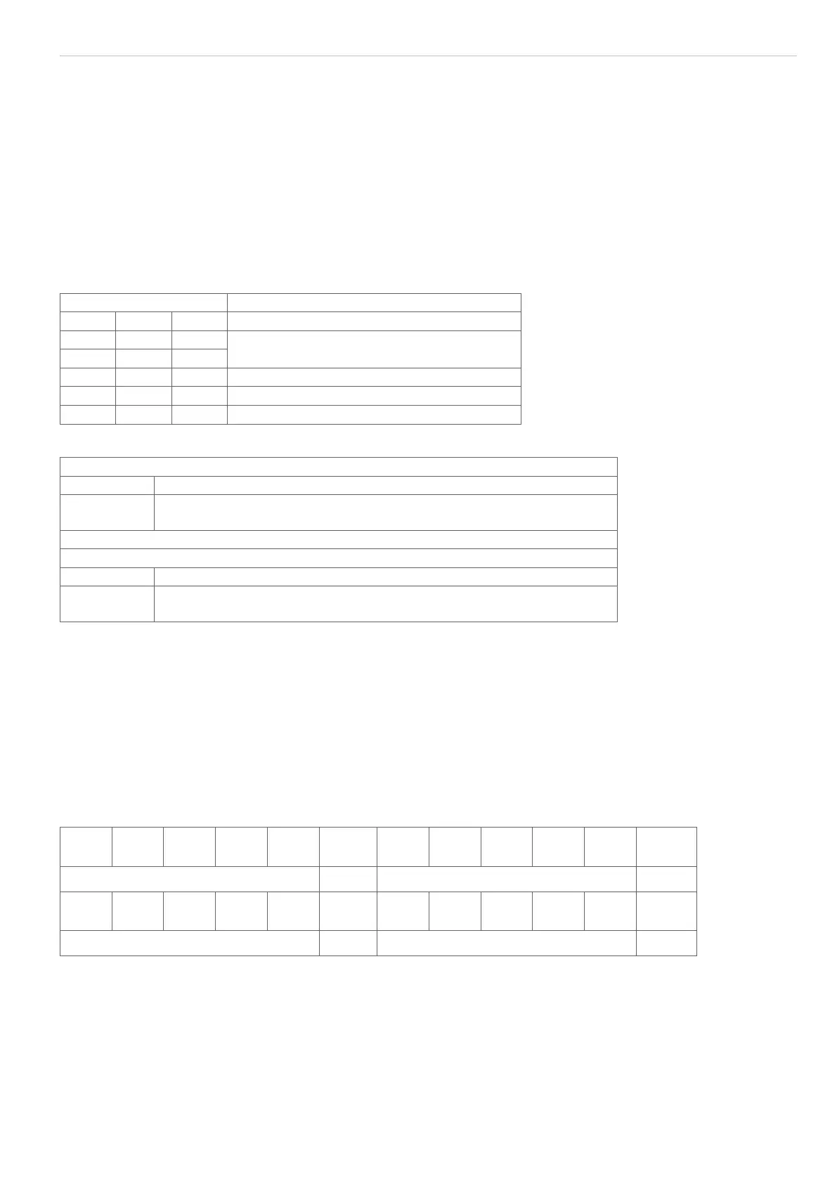
The relationship between the selected baud rate and the measuring rate is illustrated in following table, see Fig. 42:
Baud rate (kBaud) Measuring rate (measurements/second)
RS232 RS422
691.2 x 2300 (each measurement)
115.2 x
38.4 x x 766 (each 3
rd
measurement)
19.2 x x 383 (each 6
th
measurement)
9.6 x x 255 (each 9
th
measurement)
Fig. 42 Baud rates and measuring rates
RS232
Baud rate: 9.6 to 115.2 kBaud, selectable via menü RS232 baud rate
Data format: 8 data bits, parity selectable, 1 or 2 stop bits, adjustable via menu Se-
lect RS232 parameter, (standard: 8, N, 2)
RS422
Baud rate: 9.6 to 691.2 kBaud, selectable via menu RS422 baud rate
Data format 8 data bits, parity selectable, 1 or 2 stop bits adjustable via menu Se-
lect RS422 parameter, (standard: 8, N, 1)
6.6.2 Serial Measurement Output
The serial output format of the measurement can be set in the options data menu. The options are Binary and AS-
CII.
ASCII format
Twelve characters are always output as a minimum with the first five figures as standard corresponding to the digital
value of the measurement and being continuously output.
In the Multi-segment program a further 5 figures are needed for each further segment.
Figures 1 - 5 are occupied with 0 ... 65535. For the computation formula of the measurement, see Binary mea-
surement output.
Figure
1
Figure
2
Figure
3
Figure
4
Figure
5
0x09 Figure
1
Figure
2
Figure
3
Figure
4
Figure
5
0x09
Measurement value (1. segment) <Tab> 2. segment <Tab>
Figure
1
Figure
2
Figure
3
Figure
4
Figure
5
0x09 Figure
1
Figure
2
Figure
3
Figure
4
Figure
5
0x0D
3. segment <Tab> 4. segment <CR>
The measured values are separated with a tab character (0x09).
Finally a <CR> („carriage return“, 0D) is attached to the string.

 Loading...
