Page 23
Measure
optoCONTROL 2600
6. Operation
6.1 Initial Operation
Connect the light source and receiver to the controller before the system is put into
operation, see Fig. 5, and fix all connectors secured with the screw connections.
Turn on on downstream computers.
Switch on the 24 V DC supply voltage at the controller.
As delivered, the measurement system is programmed to the standard setting of “Edge
bright - dark”. If there is no target in the beam path, then the red LED (Error) lights.
i
Observe a warm-up period of 30 minutes.
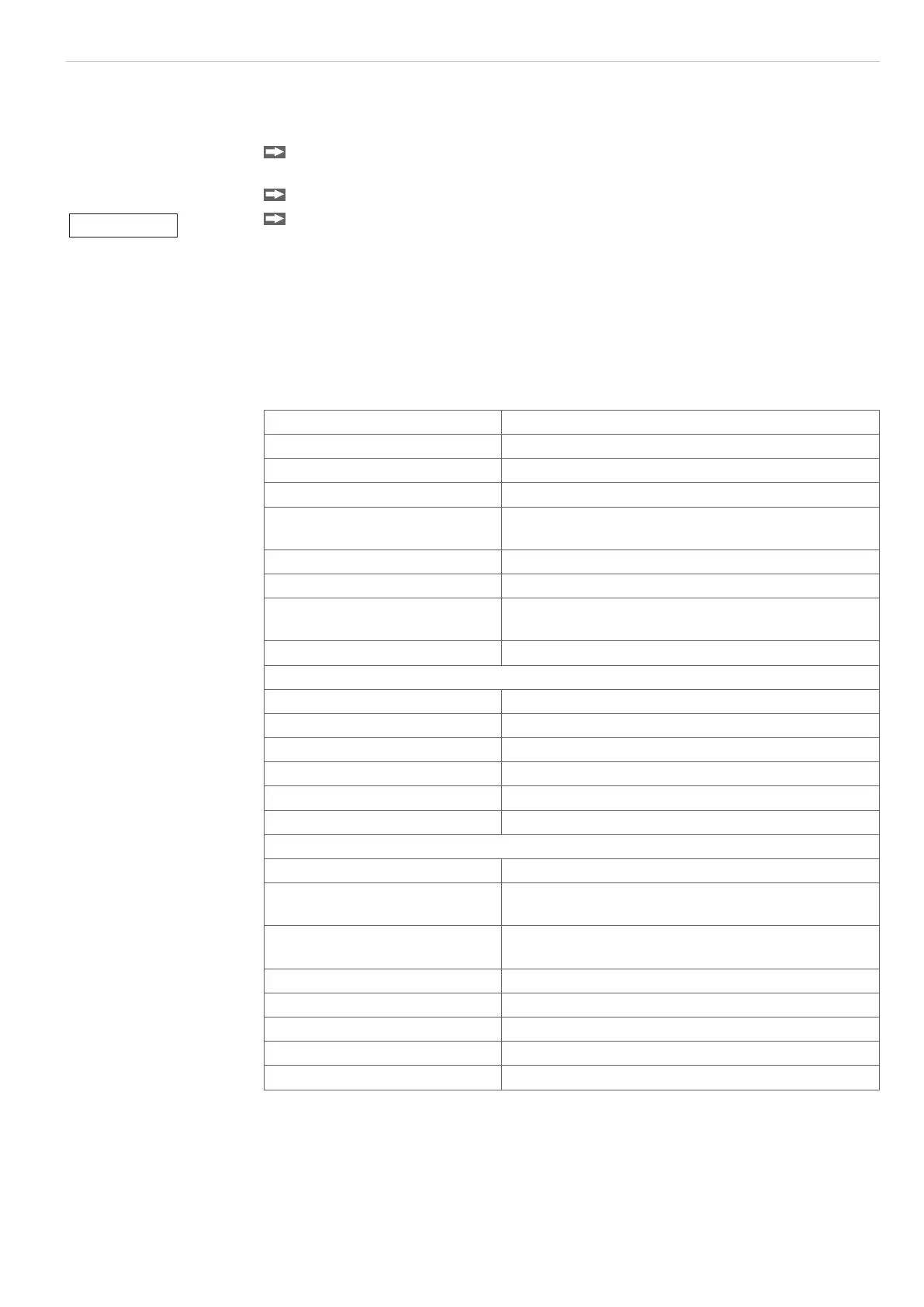
6.2 Menu Structure
A detailed representation of the operating concept can be found in the annex, see A 5.
Select options Contrast
Language
Measurement unit (mm or inch)
Error handling (analog output)
Interface parameters
(active interface, RS232 or RS422)
External light control (LED On/Off)
Clear user data
Video (for adjustment, light reference tuning and
threshold adjustment)
Service menu
Select measurement program: Edge bright - dark
Edge dark - bright
Diameter / width
Gap
Segment and multisegment
User-defined programs (four max.)
Edit measurement program Master value
Select segments (only for segment and multiseg-
ment measurement programs)
Offset / gain, separately for display and analog
output
Upper tolerance limit / lower tolerance limit
Upper warning level / lower warning level
Median
Averaging
Measurement mode
NOTICE
During the operation, i.e.
with the supply voltage
switched on, the light
source and receiver must
not be unplugged.
> Risk of damage to
light source / receiver
or the controller

 Loading...
