Page 9
Measure
optoCONTROL 2600
3.3 Controller
3.3.1 Front View of the Controller
The interactive operation is supported by an LC graphical display with illuminated
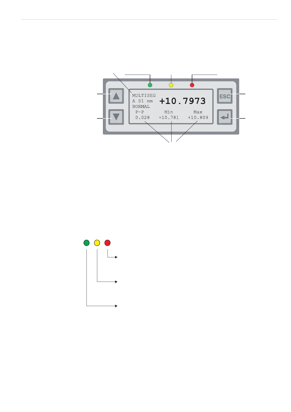
screen. The controller is operated with the four keys on the front panel, see Fig. 3.
LED green
System ready
LED yellow
Light ON
LED red
Error
Operating mode
Multi segment
31
42
Statistic values
Fig. 3 Keypad and display on the front panel of the controller
The following functions are assigned to the keypad, see Fig. 3:
(1), (2) Up/down movement in menus,
Value input: (1) greater, (2) smaller
(3) Quitting a menu point, change to the next higher hierarchical level
(4) Entry into the selected menu point, confirmation of entry (By long press switches the
input values are taken over.)
Below the operating mode (e.g. DIA, EDGE) A for absolute or R for relative measurement
is displayed.
- In the Multisegment operating mode (MULTISEG) the code for the selected seg-
ment also appears (S1 or S2).
LED red lights Error
LED yellow
LED grün lights
lights
Measurement operation, Light ON
Menu operation, Light ON
System in operation
Fig. 4 LEDs on the front panel of the controller
 Loading...