Page 22
Measure
optoCONTROL 2600
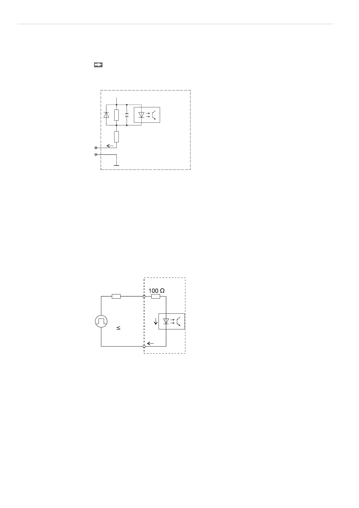
5.7 Switching Inputs
Light source off, Zero-point inputs are, for example, connected through relay contacts or
transistors (optocouplers).
Activate the light source switch-off in the relevant menu!
All GND signals are connected together internally and with the minus pole (GND) of the
24 V supply voltage.
3k3
GND
+24 V
I 7 mA
Controller
Fig. 23 Basic circuit for switching inputs
5.8 Synchronal Signal Input
The input is triggered by a further controller or another device.
R
ext
(V
HIGH
- V
F
- (I
LED
* 100 Ohm)) / I
LED
Example V
HIGH
= 3.3 V
I
LED
= 15 mA
V
F
= 1 V
R
ext
= 53.3 Ohm, also 56 Ohm
All GND signals are connected together internally and with the minus pole (GND) of the
24 V supply voltage.
Controller
I
LED
V
F
24
12
R
ext
V
High
0.8 V
V
Low
Fig. 24 Circuit synchronal signal input, 25-pol. Sub-D

 Loading...
