Page 32
Measure
optoCONTROL 2600
6.3.7.5 Limit Monitoring
The controller can compare the measurement with four different limits.
Therefore, thresholds can be monitored, impermissible tolerances detected and sorting
criteria realized.
The reference value is always the averaged measurement.
Exception: If 1 is selected for “No. of readings for forming average”, each measurement
is a reference value.
The detected upper and lower limit violations activate the associated switching output at
the full measuring rate of 2.3 kHz.
In addition, they are shown in the display (top right-hand corner in the Full display).
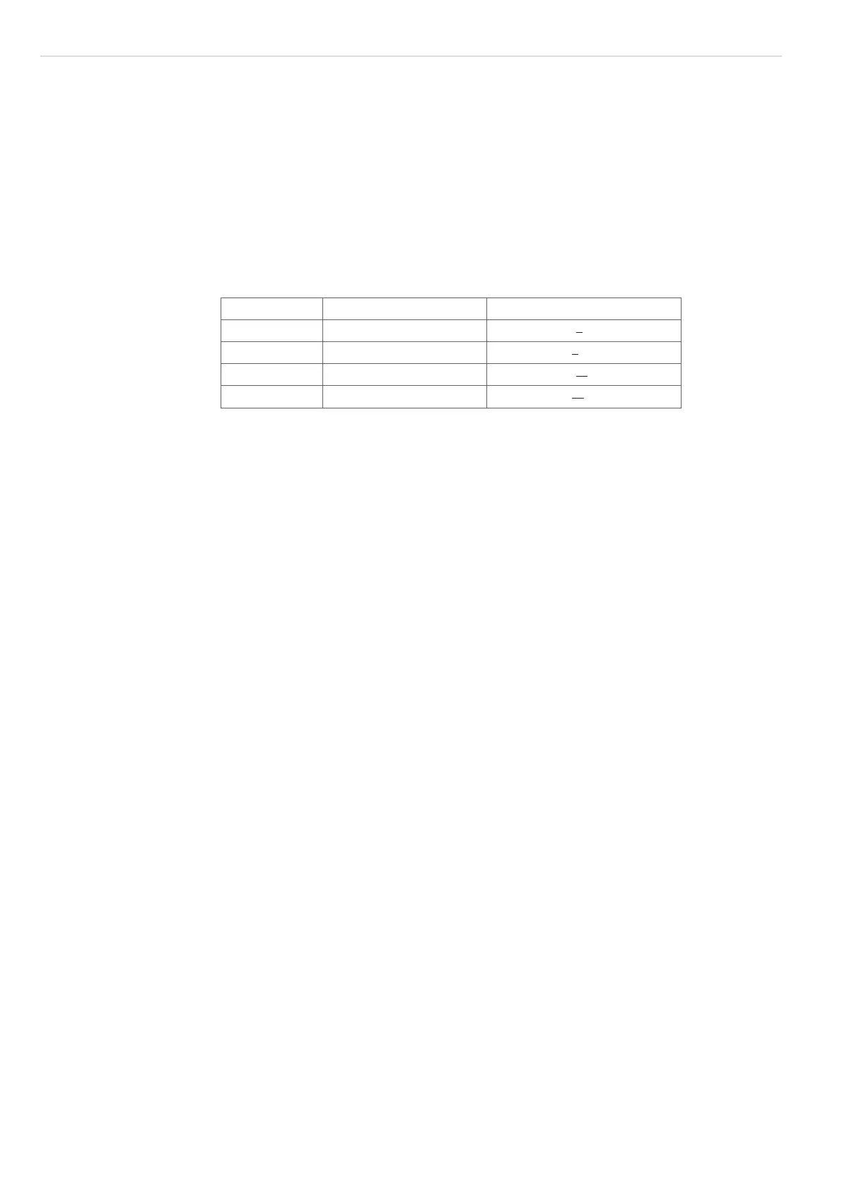
Abbreviation Standard Multi-segment
HW Higher warning level Higher limit 1
st
segment
LW Lower warning level Lower limit 1
st
segment
HL Higher tolerance limit Higher limit 2
nd
segment
LL Lower tolerance limit Lower limit 2
nd
segment
Fig. 31 Limit allocation
Remark:
The limit output of the Multi-segment measurement program differs from the other
standard programs. For the segment 1 + 2 one upper and one lower limit can be de-
fined.
6.3.7.6 Averaging
In the measurement system averaging can take place over a selectable number of
consecutive measurements. Here, the sliding average is used with a number from 1 to
128 and the recursive average from 129 to 4096. The setting of the averaging number is
described in Chapter Editing the Measurement Program, see A 5.6.
6.3.7.7 Median Filter
The median filter over n measurements selects in each case the mean value from the n
values and eliminates the odd “runaway” value.
Any additionally set averaging occurs after the median filter.
The setting of the filter sizes 3, 5, 7 or 9 and switching off the filter are described in Chap-
ter Editing the Measurement Program, see A 5.6.

 Loading...
