Page 65
Appendix | Other Pin Assignments
optoCONTROL 2600
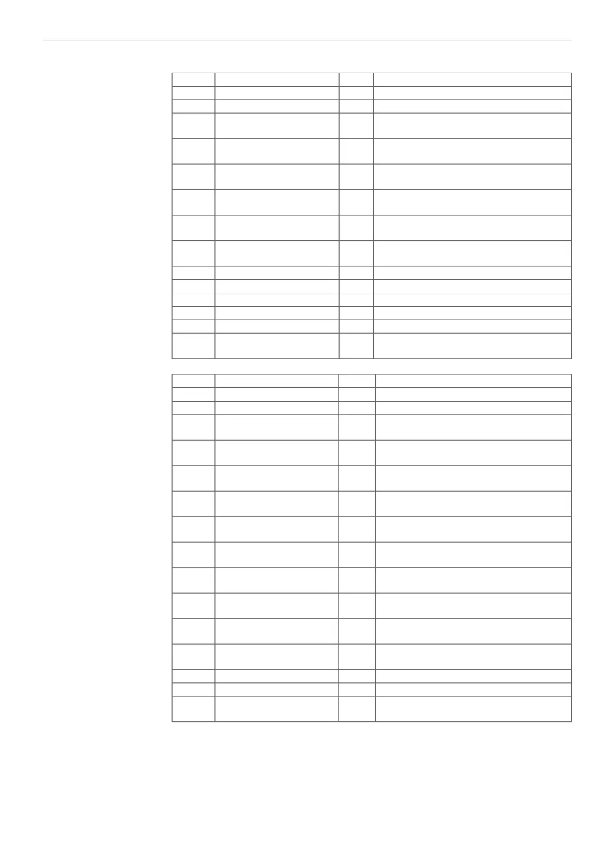
A 3.2 Cable for RS232 and RS422
25-pin. Signal 9-pin Braids
1 Error output (signal) red
14 Error output (GND) blue
2 Upper tolerance limit
(signal)
purple
15 Upper/lower tolerance
(GND)
black and brown
3 Lower tolerance limit
(signal)
white
16 Upper warning limit (sig-
nal)
pink
4 Upper/lower warning limit
(GND)
gray and gray / pink
17 Low warninging limit
(signal)
red / blue
9 RS232 reception (RxD) 3
22 RS232 DGND 5
10 RS232 transmission (TxD) 2
25 Analog output (AGND) black (inner conductor)
13 Analog output (signal) green
black (outer shield on 25-pin connector
housing)
Fig. 57 SCD2500-x/3/RS232 pin assignment
25-pin Signal 15-pin Braids
1 Error output (signal) red
14 Error output (GND) blue
2 Upper tolerance limit
(signal)
purple
15 Upper/lower tolerance
(GND)
black and brown
3 Lower tolerance limit
(signal)
white
16 Upper warning limit
(signal)
pink
4 Upper/lower warning limit
(GND)
gray and gray / pink
17 Lower warning limit (sig-
nal)
red / blue
20 RS422 reception (negat-
ed)
1
7 RS422 reception (posi-
tive)
2
8 RS422 transmission
(positive)
4
21 RS422 transmission
(inverted)
3
25 Analog output (AGND) black (inner conductor)
13 Analog output (signal) green
black (outer screen on connector housing
25-pin)
Fig. 58 Pin assignment SCD2500-x/3/RS422

 Loading...
