Page 17
Measure
optoCONTROL 2600
85.5
(3.37)
190.5
(7.5)
290.5
(11.4)
390.5
(15.37)
524.5
(20.64)
602.5
(23.7)
610
(24)
45 (1.77)
40 (1.57)
37.5 (1.48)
26.5 (1.04)
7.5 (.30)
5 (.20)
0
7.5
(.30)
ø6.6 (.26 dia.)
ø11 (.43 dia.)
ø3K7 (.1)
ø8 (.31)
ø4.5 (.18 dia.)
0
Fig. 15 Dimensional drawing of the mounting rail, option 209
Dimensions in mm (inches)
i
The light source and receiver must be aligned with one another using the video signal.
When the sensor components, light source and receiver, are mounted freely, initially exact alignment of the housing
edges with respect to one another should be ensured. The housing
edges must lie within one plane.
The angular deviation may be up to 0.25 °. For alignment try squares or rails are suitable aids.
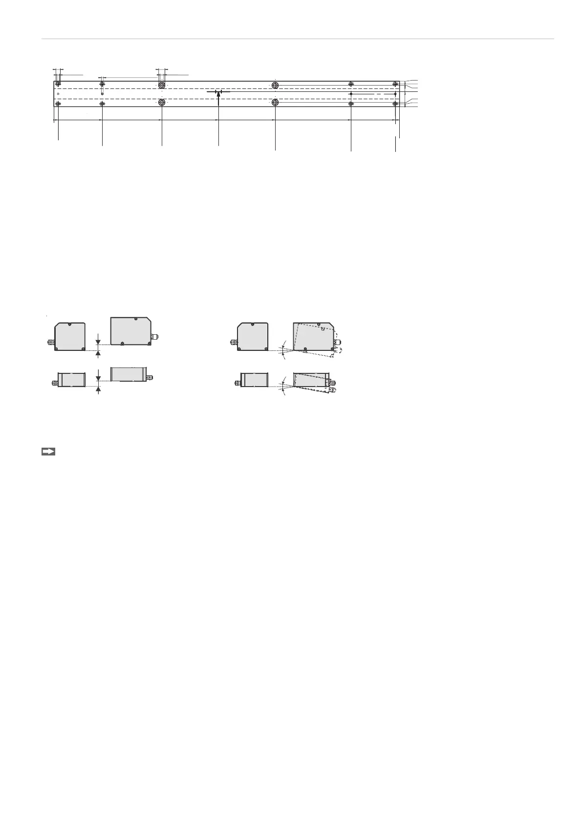
Tolerances for maximum moving and tilting of the light source and receiver during installation and mounting. The
following illustrations show the permissible error range:
0.5 mm
0.5 mm
max. ±0.25 °
max. ±0.25 °
Offset: Maximum 0.5 mm Tilt: Maximum 0.25 °
Fig. 16 Permissible adjustment error
Connect light source and receiver with the controller.
Use the video signal, see 6.3.4, for accurate adjustment of the light source and receiver.

 Loading...
