Home
MICRO-EPSILON
Measuring Instruments
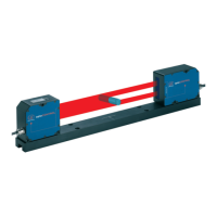
optoCONTROL 2600
MICRO-EPSILON optoCONTROL 2600 User Manual
4
of 1
of 1 rating
82 pages
Give review
Manual
Specs
To Previous Page
To Previous Page
Loading...
MICRO-EPSILON Eltrotec GmbH
Manfred-
Wörner
-Straße 101 · 73037 Göppingen / Germany
T
el. +49 (0) 7161 / 98872-300 · Fax +49 (0) 7161 / 98872-303
eltrotec@micro-epsilon.com · www
.micro-epsilon.com
Y
our local contact:
www
.micro-epsilon.com/contact/worldwide/
X9751125-B062101HDR
MICRO-EPSILON MESSTECHNIK
81
Table of Contents
Table of Contents
3
Safety
5
Symbols Used
5
Warnings
5
Notes on CE Marking
5
Intended Use
6
Proper Environment
6
Light Source
7
Functional Principle, Technical Data
8
Measurement Principle
8
Structure of a Complete Measurement System
8
Controller
9
Front View of the Controller
9
Rear View of the Controller
10
Operating Modes
10
Technical Data
11
Block Diagram
12
Analog Output
12
Input Zero Point / RESET
12
Synchronization
12
Error Output
13
Light Source Control and Trigger Input
13
Edge Detection Threshold for Transparent Measurement Objects
13
Delivery
14
Unpacking, Included in Delivery
14
Storage
14
Installation and Mounting
15
Precautions
15
Mounting the Sensor Unit
15
Mounting the Controller
18
Power Supply
19
Connecting an Analog Terminal Device
19
Switching Outputs
21
Switching Inputs
22
Synchronal Signal Input
22
Operation
23
Initial Operation
23
Menu Structure
23
Operation
24
Key Functions
24
Display
24
Main Menu
24
Adjustment with the Video Signal
25
Options
25
Select Measurement Program
26
Edit Measurement Program (User-Specific Programs)
28
Zero-Setting Function
29
Mastering
30
Measurement Programs Segment and Multi-Segment
30
Display Scaling
31
Limit Monitoring
32
Averaging
32
Median Filter
32
Measurement Modes
33
Analog Output
36
Setup
36
Measurement Conversion
36
Error Handling
37
Synchronization of Optocontrols
37
Digital Interfaces
39
Interface Parameters
39
Serial Measurement Output
39
Control Commands
41
Information Command
43
Start Command
43
Stop Command
44
Reset Command
44
Change the Measurement Program
45
Change Edges (Segment and Multi-Segment Programs)
46
Read out Min/Max Values
46
Read out Min/Max Values Followed by Reset
47
Read Option Data
48
6.6.3.10 Write Option Data
48
6.6.3.11 Save Option Data
50
6.6.3.12 Read Measurement Program Data
51
6.6.3.13 Write Measurement Program Data
52
6.6.3.14 Save Measurement Program Data
54
6.6.3.15 Resetting the Output Values in the Trigger Measurement Mode
54
6.6.3.16 Activating the Output in the Trigger Measurement Mode
55
6.6.3.17 Activating the Light Reference Tuning
55
6.6.3.18 Reset the Light Reference Tuning
56
Error Responses
56
Timing
57
Error Effects
58
Error Effects on the Light Beam
58
Extraneous Light
58
Contamination
59
Transparent Target Objects
59
Reduced Light Intensity
60
Show Software Version
61
Disclaimer
61
Service, Repair
61
Decommissioning, Disposal
61
Appendix
62
A 1 Optional Accessories
62
A 2 Factory Setting
63
Other Pin Assignments
64
Cables for Analog Terminal Devices
64
Cable for RS232 and RS422
65
A 3.3 Interface Card IF2008/PCIE
66
Software Support with Medaqlib
68
A 5 Operating Menu
69
A 5.1 Initialization and Operation in the Measurement Mode
69
A 5.2 Dialog and Procedure for Saving
70
A 5.3 Options (General Settings)
71
A 5.4 Options (Interface)
73
A 5.5 Selecting the Measurement Program
75
A 5.6 Editing the Measurement Program
76
Limits with the Multi-Segment Measurement
79
A 6 Standard Measurement Program Data for ODC2600-40
80
4
Based on 1 rating
Ask a question
Give review
Questions and Answers:
Need help?
Do you have a question about the MICRO-EPSILON optoCONTROL 2600 and is the answer not in the manual?
Ask a question
MICRO-EPSILON optoCONTROL 2600 Specifications
General
Brand
MICRO-EPSILON
Model
optoCONTROL 2600
Category
Measuring Instruments
Language
English
Related product manuals
MICRO-EPSILON ILD1402-5
78 pages
MICRO-EPSILON capaNCDT 6200
20 pages