© Microhard Systems Inc. 22
3.0 Hardware Features
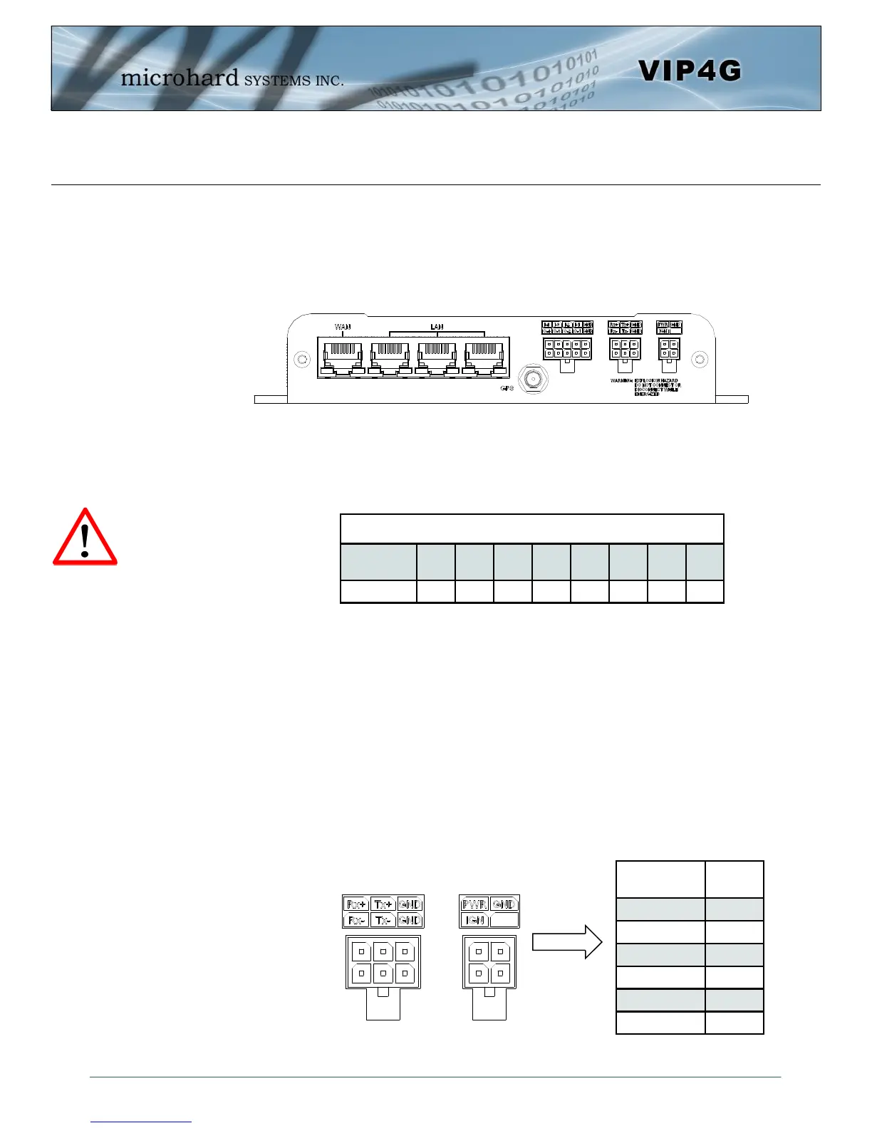
3.1.2 Connections
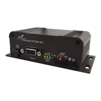
3.1.2.1 Front
On the front of the VIP4G Series are, from left to right:
WAN port
10/100/1000 Ethernet RJ45 Connection.
802.3af Passive PoE (WAN port only)
LAN port
3x - 10/100/1000 Ethernet RJ45 Connection.
GPS
SMA Female
Digital I/O Connector 10-Pin: (Use AMP MATE-N-LOK PN# 1-794617-0)
I-4, I-3, I-2, I-1, GND
O-4, O-3, O-2, O-1, GND
RS485/422 Connector 6-Pin: (Use AMP MATE-N-LOK PN# 794617-6)
Rx+, Tx+, GND
Rx-, Tx-, GND
Power Connector 4-Pin: (Use AMP MATE-N-LOK PN# 794617-4)
PWR, GND
IGN - Ignition signal for Power Saving Mode*
Caution: Using a
power supply that
does not provide
proper voltage may
damage the VIP4G
unit.
Drawing 3-4: VIP4G Front View
Ethernet RJ45 Connector Pin Number
Source
Voltage
1 2 3 4 5 6 7 8
9 - 30 Vdc Data Data Data DC+ DC+ Data DC- DC-
Table 3-1: WAN PoE Connections
Name
Input or
Output
TxB (D+) O
TxA (D-) O
RxB (R+) I
RxA (R-) I
GND -
PWR + I
Table 3-2: Data RS422/485
Vin Pin Assignment
* Power Saving Mode only available on select units, must be
specified at time of order or returned to factory for upgrade.